Collision energy absorbing device of railcar
- Summary
- Abstract
- Description
- Claims
- Application Information
AI Technical Summary
Benefits of technology
Problems solved by technology
Method used
Image

Examples
Embodiment Construction
[0018]Hereinafter, an embodiment will be explained in reference to the drawings.
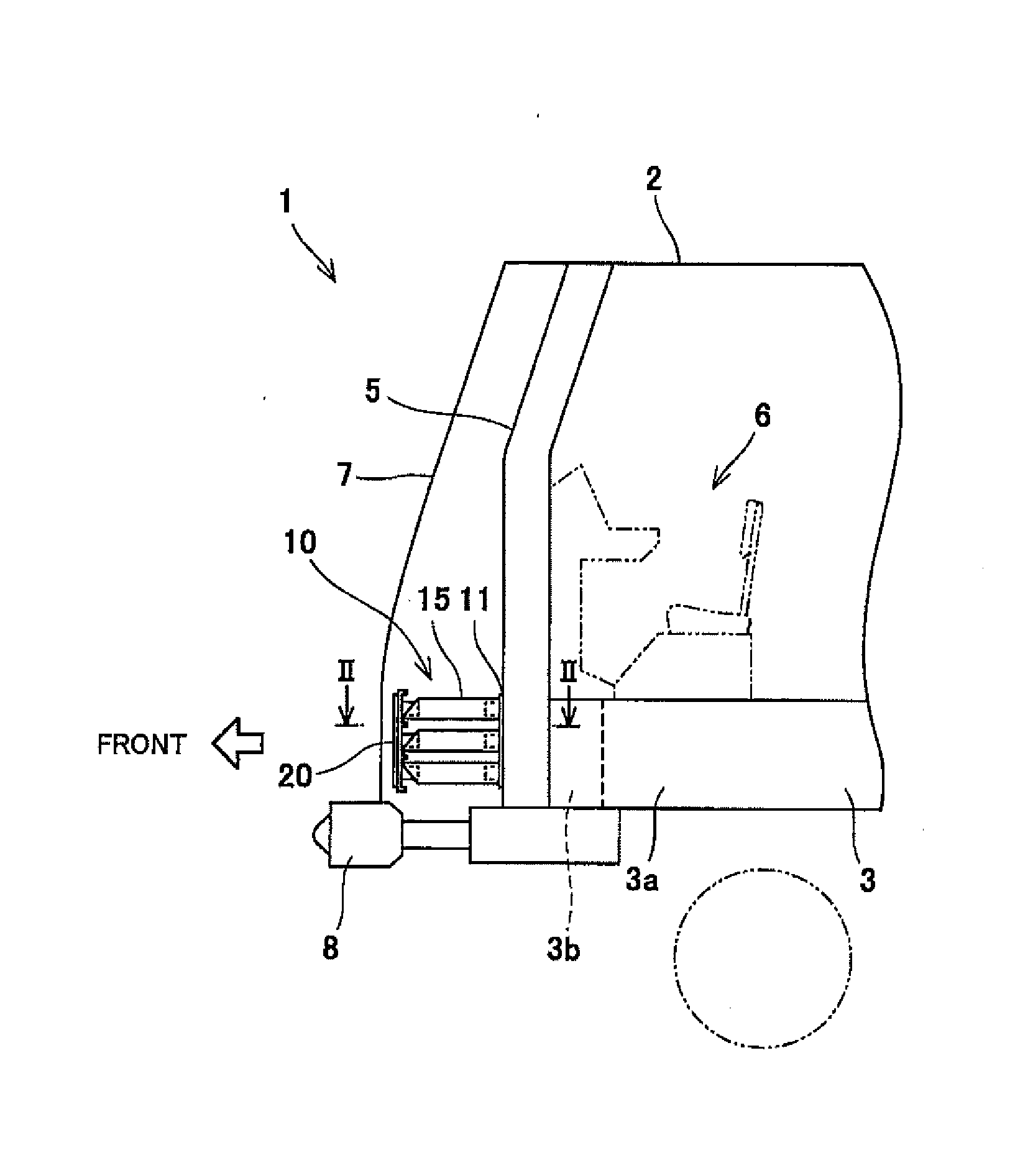
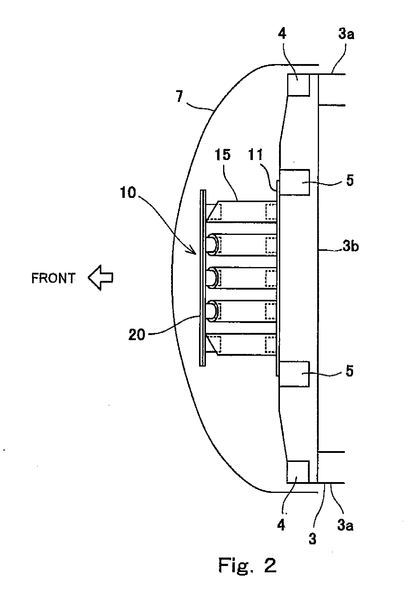
[0019]FIG. 1 is a cross-sectional view showing a head portion of a railcar 1 including a collision energy absorbing device 10 according to an embodiment. FIG. 2 is a cross-sectional view taken along line II-II of FIG. 1. As shown in FIGS. 1 and 2, the collision energy absorbing device 10 is fixed to a front portion of a bodyshell 2 of a head car of the railcar 1 so as to project in a forward direction. With this, for example, when cars traveling on the same railway track collide head-on with each other or a car collides with an obstacle, the collision energy absorbing device 10 is crushed by a load from a front side to absorb collision energy.
[0020]The bodyshell 2 includes an underframe 3. The underframe 3 includes: a pair of left and right side sills 3a extending in a forward / rearward direction; and an end beam 3b coupling front ends of the left and right side sills 3a to each other and extending in a l...
PUM
 Abstract
Description
Claims
Application Information
 - R&D
- Intellectual Property
- Life Sciences
- Materials
- Tech Scout
- Unparalleled Data Quality
- Higher Quality Content
- 60% Fewer Hallucinations
Browse by: Latest US Patents, China's latest patents, Technical Efficacy Thesaurus, Application Domain, Technology Topic, Popular Technical Reports.
© 2025 PatSnap. All rights reserved.Legal|Privacy policy|Modern Slavery Act Transparency Statement|Sitemap|About US| Contact US: help@patsnap.com