Steering system

a steering system and buffer material technology, applied in the direction of steering parts, vehicle components, transportation and packaging, etc., can solve the problem of likely falling off of stopper buffer material, and achieve the effect of stable absorption

Active Publication Date: 2018-07-03
JTEKT CORP
View PDF12 Cites 9 Cited by
  • Summary
  • Abstract
  • Description
  • Claims
  • Application Information

AI Technical Summary

Benefits of technology

[0006]An object of the invention is to provide a steering system in which a buffer member serving as a stopper is less likely to come off and in which, at the time of abutting contact, a possible impact can be stably absorbed.

Problems solved by technology

In this case, an impact may make the stopper buffer material likely to come off.

Method used


Image

  • Steering system
  • Steering system
  • Steering system

Examples


Embodiment Construction

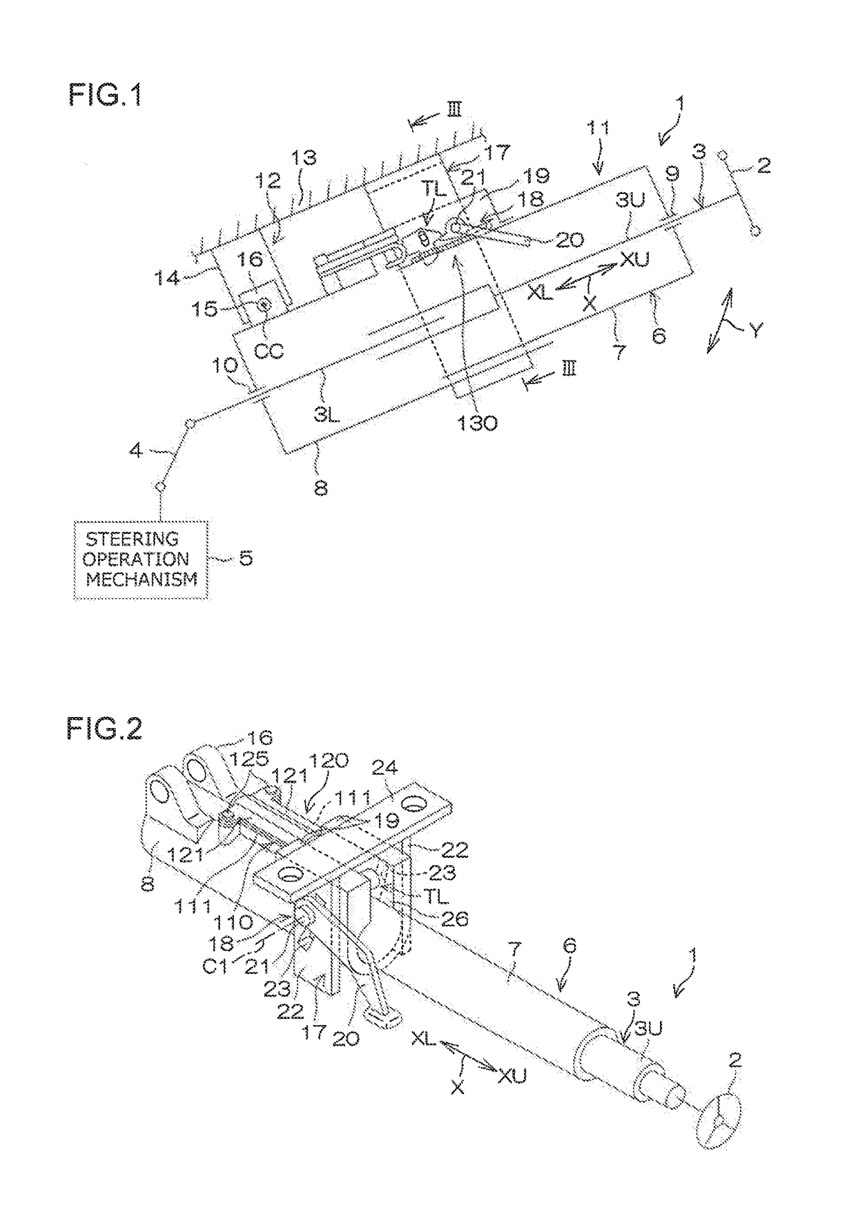
[0017]An embodiment of the present invention will be described below in detail. FIG. 1 is a schematic side view of a steering system 1 according to the embodiment of the present invention. As seen in FIG. 1, a steering system 1 includes a steering shaft 3, a column jacket 6, an intermediate shaft 4, and a steering operation mechanism 5. A steering member 2 such as a steering wheel is coupled to a first end (axially upper end) of the steering shaft 3. The steering system 1 steers steered wheels (not depicted in the drawings) in conjunction with steering of the steering member 2. The steering operation mechanism 5 is a rack-and-pinion mechanism but is not limited to the rack-and-pinion mechanism.

[0018]In the following description, an axially upper side XU refers to an upper side in a column axial direction X that is an axial direction of the steering shaft 3, and an axially lower side XL refers to a lower side in the column axial direction X. The steering shaft 3 has a tubular upper s...


PUM


Abstract

A steering system enabling telescopic adjustment within a predetermined range includes a second tooth member supported by a lower jacket, a damper fixed to an upper jacket so as to face the second tooth member, and an abutting contact member fixed to the lower jacket and coming into abutting contact with the second tooth member from a side opposite from a side where the damper faces the second tooth member. The damper includes an inclined surface that is located at a portion (an end) of the damper, which faces the second tooth member and that is inclined so as to gradually be closer to the upper jacket toward the second tooth member. During telescopic adjustment, the second tooth member comes into abutting contact with the inclined surface of the damper at a sliding limit position.

Description

INCORPORATION BY REFERENCE[0001]The disclosure of Japanese Patent Application No. 2016-030136 filed on Feb. 19, 2016 including the specification, drawings and abstract, is incorporated herein by reference in its entirety.BACKGROUND OF THE INVENTION1. Field of the Invention[0002]The invention relates to a steering system.2. Description of the Related Art[0003]In many known steering systems, a tilt adjustment mechanism or a telescopic adjustment mechanism is assembled. The tilt adjustment mechanism adjusts the height and angle of a steering wheel. The telescopic adjustment mechanism adjusts the position of the steering wheel in a front-rear direction. In a conventional telescopic adjustment mechanism, telescopic adjustment is performed by moving a movable bracket installed on a steering column in an axial direction of the steering column with respect to a fixed bracket installed at a predetermined position in an interior of a vehicle. A moving range of the movable bracket during the t...

Claims


Application Information

Patent Timeline
Patent Type & Authority Patents(United States)
IPC IPC(8): B62D1/184B62D1/185B62D1/187
CPCB62D1/184B62D1/187B62D1/185B62D1/195
Inventor NAGATANI, ATSUMUNEMYOHOJI, YU
Owner JTEKT CORP
Why Eureka
Try Eureka