Method for mechnical and electrical connection to display electrodes

a technology of electrical connection and electro-optic display, which is applied in the direction of optics, coupling device connection, instruments, etc., can solve the problems of high cost and time-consuming of current methods for assembling an electro-optic display to a pcb

Active Publication Date: 2016-12-29
E INK CORPORATION
View PDF7 Cites 21 Cited by
  • Summary
  • Abstract
  • Description
  • Claims
  • Application Information

AI Technical Summary

Benefits of technology

[0005]According to an aspect of the present application, an electro-optic display is provided, comprising a front electrode, the front electrode having a first opening defined therein, and a rear electrode, the rear electrode having a second opening defined therein. The electro-optic display further comprises an electro-optic layer between the front and rear electrodes. The electro-optic display further comprises a rigid conductive comp...

Problems solved by technology

Currently used methods to assemble an electro-opt...

Method used


Image

  • Method for mechnical and electrical connection to display electrodes
  • Method for mechnical and electrical connection to display electrodes
  • Method for mechnical and electrical connection to display electrodes

Examples


Embodiment Construction

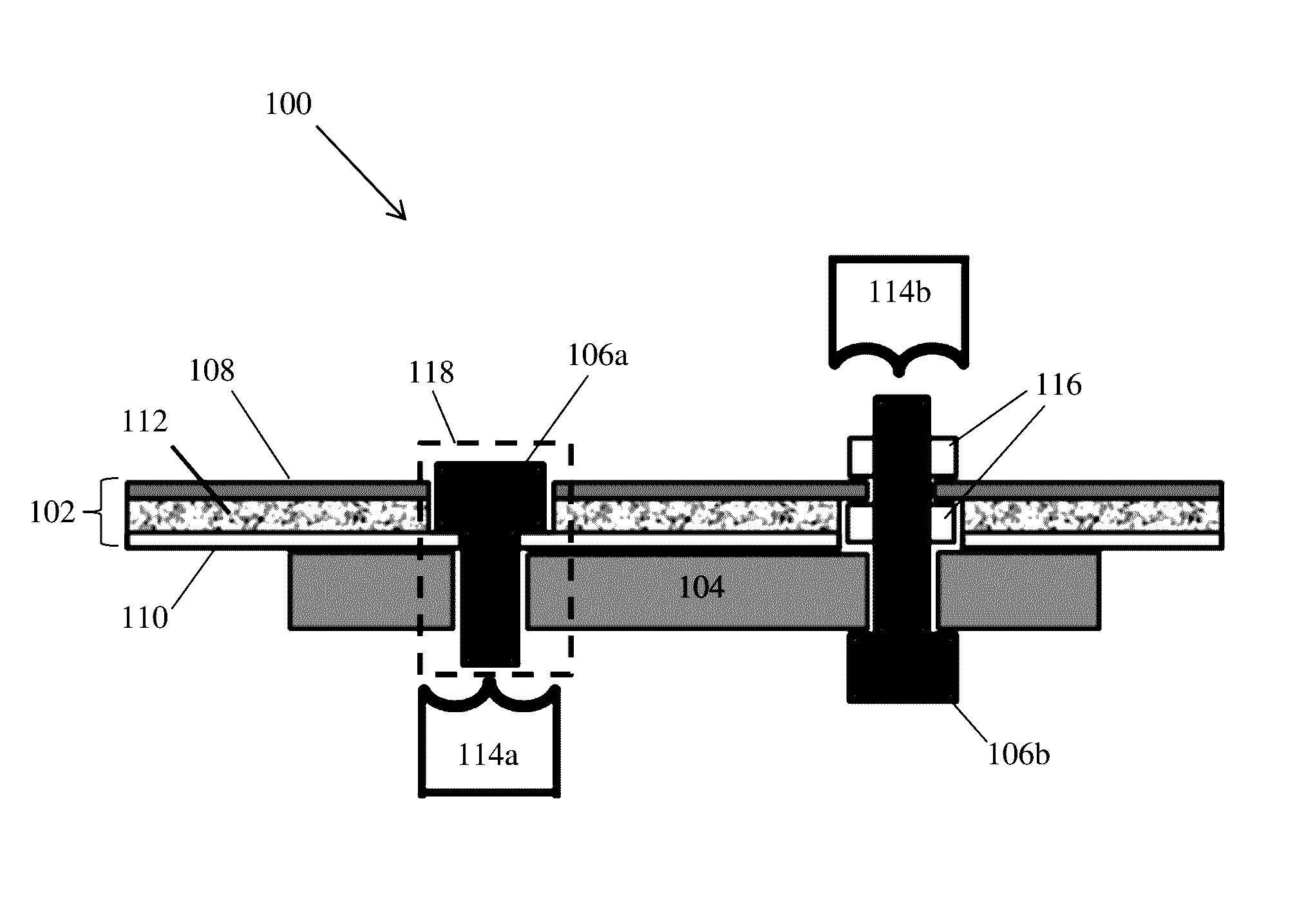
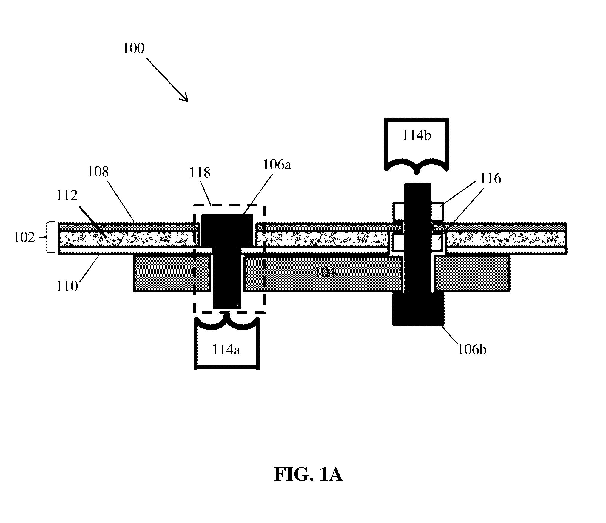
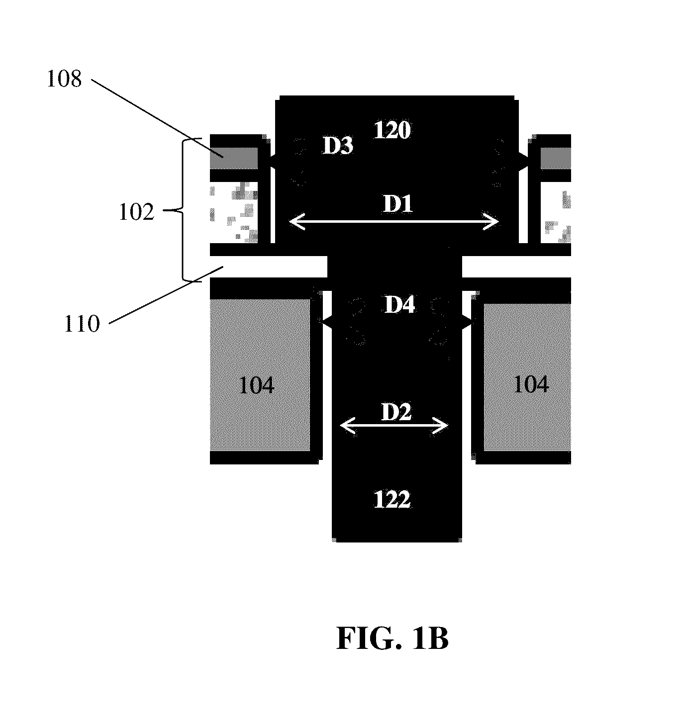
[0014]Aspects of the present application relate to connectors for electro-optic displays providing both mechanical and electrical interconnection, with at least some aspects providing a connector configured to pass through opposing electrodes of the electro-optic display while providing electrical connection between one of the electrodes and a control circuit (also referred to herein as a “driver circuit”). Some electro-optic displays include two, opposing electrodes between which is an electro-optic layer, such as an electrophoretic layer. The optical state of the electro-optic layer may be controlled by application of suitable signals, such as voltages, to the electrodes. Aspects of the present application relate to connectors which provide electrical connection to one or both of the electrodes. In some embodiments, the connector may be a rigid, conductive connector, such as a rivet or a bolt. The connector may pass through both electrodes but electrically contact only one of the ...


PUM


Abstract

An electro-optic display may comprise a front electrode having a first opening defined therein, a rear electrode having a second opening defined therein, an electro-optic layer between the front and rear electrodes and a rigid conductive component passing through the first and second openings and electrically contacting the front electrode but not the rear electrode.

Description

REFERENCE TO RELATED APPLICATIONS[0001]This application claims benefit of Provisional Application Ser. No. 62 / 186,044, filed Jun. 29, 2015.BACKGROUND OF INVENTION[0002]This invention relates to mechanical and electrical connections for electro-optic displays, and to methods for assemble such displays. The connection means of the present invention are especially, but not exclusively, intended for use with particle-based electrophoretic displays in which one or more types of electrically charged particles are suspended in a liquid and are moved through the liquid under the influence of an electric field to change the appearance of the display.[0003]Connection means such as rivets and bolts are frequently used a mechanical and electrical connectors on printed circuit boards (PCB). For example, rivets are used as low cost solder free option requiring minimal time and labor. The material and labor cost of bolts and / or nuts can be higher, but they allow for later disassembly and repair.[0...

Claims


Application Information

Patent Timeline
IPC IPC(8): G02F1/167H01R4/06H01R4/30H01R12/70G02F1/1676
CPCG02F1/167H01R12/7076G02F2001/1676H01R4/30H01R4/06G02F1/1676G02F1/1675H01R12/523G02F1/13452G02F2201/42G02F2201/46G02F1/16753
Inventor HARRIS, GEORGE G.
Owner E INK CORPORATION
Why Eureka
Try Eureka