Image forming apparatus for forming image on sheet

Active Publication Date: 2016-12-29
CANON KK
View PDF3 Cites 2 Cited by
  • Summary
  • Abstract
  • Description
  • Claims
  • Application Information

AI Technical Summary

Benefits of technology

[0006]The present invention detects over stacking of sheets more accurately than with conventional techniques. The present invention provides an image forming apparatus comprising the following elements. A stacking unit in which a sheet is stacked. A conveyance unit is configured to convey the sheet. A time-counting unit is conf

Problems solved by technology

If the number of sheets that exceeds the number expected in design is stacked in these stacking units, a feeding failure may occur.
However, if the height of a bundle of envelope type sheets is detected using a sensor, over stac

Method used


Image

  • Image forming apparatus for forming image on sheet
  • Image forming apparatus for forming image on sheet
  • Image forming apparatus for forming image on sheet

Examples


embodiment 1

Configuration of Image Forming Apparatus

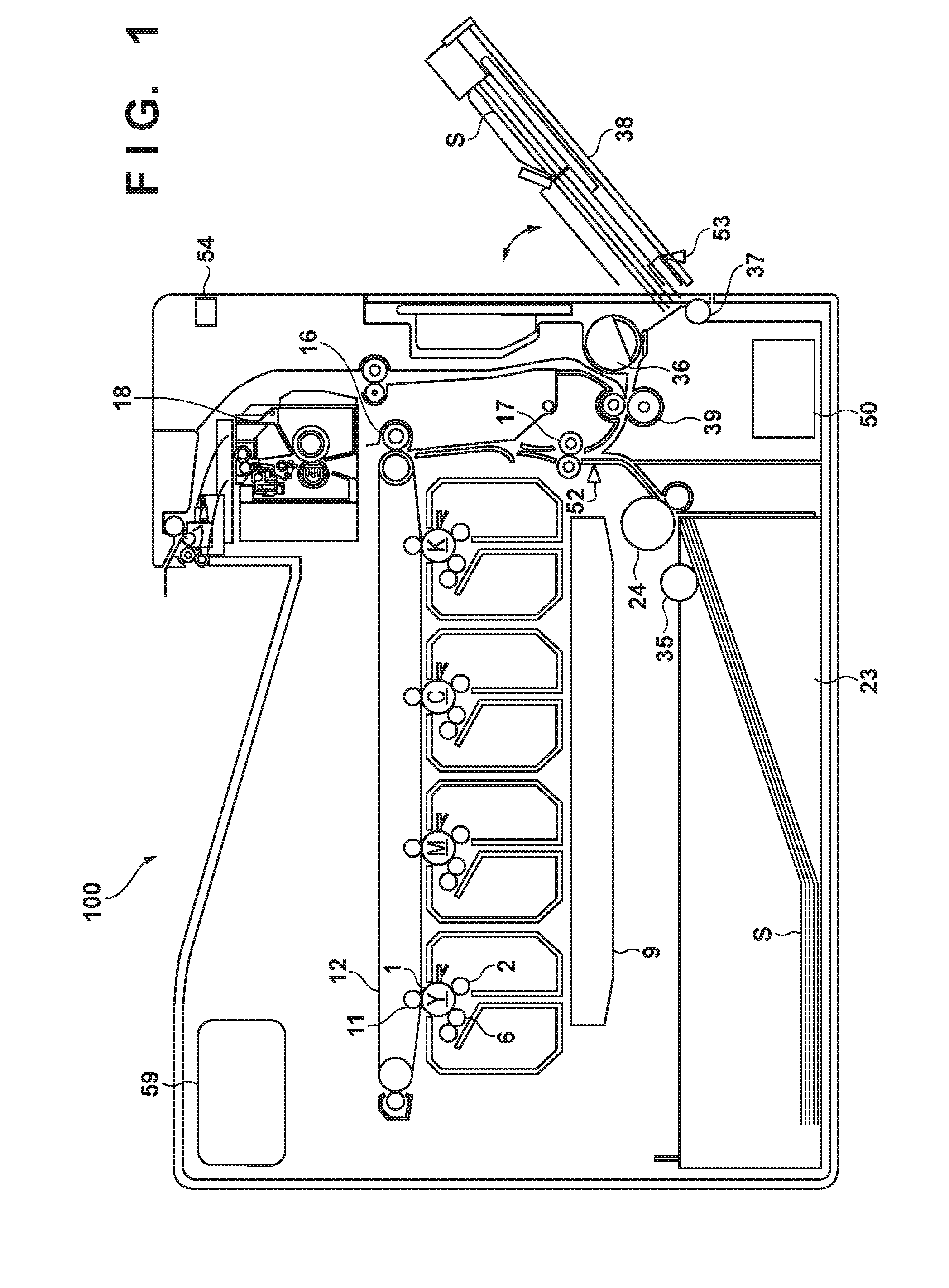
[0047]An image forming apparatus 100 will be described using FIG. 1. Although the image forming apparatus 100 according to this embodiment is an electrophotographic printer, an image forming apparatus to which the present invention is applicable may employ other image forming methods, such as an inkjet method and a thermal transfer method. The image forming apparatus 100 has four image forming units (stations), and forms toner images of yellow (Y), magenta (M), cyan (C), and black (K). In FIG. 1, referenced signs Y, M, C, and K, which are associated with the respective colors, are assigned to the four image forming units. A photosensitive drum 1 is a photosensitive member and an image carrier, and rotates clockwise at a predetermined circumferential speed (process speed). A charging roller 2 uniformly charges the surface of the photosensitive drum 1. An optical scanning device 9 outputs a light beam in accordance with an image signal. The surf...

embodiment 2

[0112]In Embodiment 1, the conveyance time T of each sheet is counted with the first feeding operation as a reference. That is to say, the conveyance time T is not reset even if a retry occurs. In Embodiment 2, the conveyance time T is reset to 0 if a retry occurs. This means that the conveyance time T is recounted from the timing at which the second feeding operation is started.

[0113]Another exemplary procedure for determining over stacking will be described in detail. Note that descriptions of items that are common to already-described items will be omitted. As described above, there are cases where, in the first feeding operation, a sheet S does not reach the flag 46 by the time the jam threshold value Tj elapses, due to a conveyance delay caused by the slipping or the rollers. However, there are cases where a sheet S reaches the flag 46 by executing the second feeding operation (retry). As shown in FIG. 18, there are cases where the leading end of the envelope E reaches the vici...

embodiment 3

[0117]According to Embodiments 1 and 2, if the conveyance time T deviates from the tolerance X, the CPU 51 determines that over stacking has occurred. However, if the resistance forces Fa and Fb generated by over stacking become too large, even the first sheet S cannot be fed. The counting of the conveyance time T can also be designed to be completed only after the leading end of a sheet S has reached the flag 46. In this case, in a state where not even a single sheet S can be fed, the conveyance time T cannot be counted, and the CPU 51 cannot determine over stacking. In this embodiment, the following over stacking determination method is introduced.

[0118][Over Stacking Determination Method]

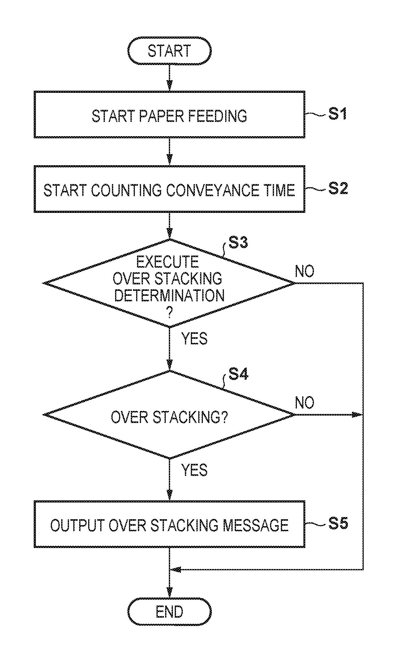
[0119]An over stacking determination method according to Embodiment 3 will be described using a flowchart in FIG. 20. Compared with FIG. 16, in FIG. 20, steps S10 and S11 are inserted between steps S2 and S3.

[0120]In step S10, the CPU 51 determines whether or not a jam has occurred. For example, ...


PUM


Abstract

An image forming apparatus may comprise the following elements. A stacking unit in which a sheet is stacked. A conveyance unit conveys the sheet. A time-counting unit counts a conveyance time from when the conveyance unit starts to convey the sheet until the sheet arrives at a predetermined position on a conveyance path. A determination unit determines that over stacking has occurred, if the conveyance time of the sheet exceeds a first over stacking threshold value.

Description

BACKGROUND OF THE INVENTION[0001]Field of the Invention[0002]The present invention relates to an image forming apparatus for forming an image on a sheet.[0003]Description of the Related Art[0004]An image forming apparatus has a stacking unit for stacking sheets. As the stacking unit, a feed cassette and a manual bypass tray provided within the image forming apparatus are used. If the number of sheets that exceeds the number expected in design is stacked in these stacking units, a feeding failure may occur. Japanese Patent Laid-Open No. 05-278896 proposes an image forming apparatus that detects over stacking by measuring the height of a sheet bundle stacked in a cassette, using a sensor.[0005]However, if the height of a bundle of envelope type sheets is detected using a sensor, over stacking is erroneously detected in some cases. Since air is likely to accumulate in an envelope type sheet, the envelope type sheet can be easily pressed down. A feed cassette is provided with a locking ...

Claims


Application Information

Patent Timeline
IPC IPC(8): G03G15/00B65H1/18B65H1/26B41J13/00
CPCG03G15/6529B65H1/266B65H1/18B41J13/0009G03G15/652G03G2215/00383G03G2215/00392G03G2215/0132B65H3/06B65H7/06B65H7/18B65H2511/30B65H2511/528B65H2601/271B65H2513/52B65H2511/15B65H2220/03B65H2220/01B65H7/20
Inventor ISOBE, KEN-ICHIROSUGANO, MICHIO
Owner CANON KK
Why Eureka
Try Eureka