Apparatus and method for real-time object monitoring

a real-time object and antenna technology, applied in antennas, radiotherapy, diagnostics, etc., can solve the problems of limiting the use of patients with large body size, wasting em energy, and limiting the use of systems, so as to reduce em radiation, accurately detect and track, and save em energy

Pending Publication Date: 2022-01-13
MEDICAL INTELLIGENCE MEDIZINTECHN
View PDF0 Cites 1 Cited by
  • Summary
  • Abstract
  • Description
  • Claims
  • Application Information

AI Technical Summary

Benefits of technology

[0003]Recent developments have been made to track an implanted device based on the generated electromagnetic (EM) field, for example biomarkers, close to a patient's tumor to report isocenter location during radiation treatment. While some systems such as disclosed in U.S. Pat. No. 9,248,003 can provide millimeter rage accuracy using wireless receivers, these systems also have significant drawbacks. For example, the wireless transceiver is required to be placed on top of the patient, which seriously limits its usage for patients with large body size, as well as navigation volume being limited by the generated magnetic field. Moreover, it blocks the beam path during radiotherapy. Other disadvantages include the patient being exposed to a significantly high dose of EM radiation and lots of EM energy is wasted due to the antenna impedance mismatch. Therefore, there is a need for a system which accurately detects and tracks a wireless marker already implanted near the patient's tumor while reducing the EM radiation to which the patient is exposed. It is the object of the present disclosure to overcome these drawbacks.

Problems solved by technology

While some systems such as disclosed in U.S. Pat. No. 9,248,003 can provide millimeter rage accuracy using wireless receivers, these systems also have significant drawbacks.
For example, the wireless transceiver is required to be placed on top of the patient, which seriously limits its usage for patients with large body size, as well as navigation volume being limited by the generated magnetic field.
Moreover, it blocks the beam path during radiotherapy.
Other disadvantages include the patient being exposed to a significantly high dose of EM radiation and lots of EM energy is wasted due to the antenna impedance mismatch.

Method used


Image

  • Apparatus and method for real-time object monitoring
  • Apparatus and method for real-time object monitoring
  • Apparatus and method for real-time object monitoring

Examples


Embodiment Construction

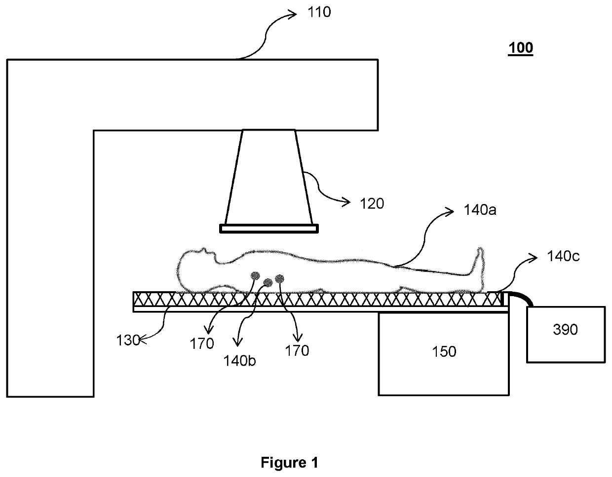
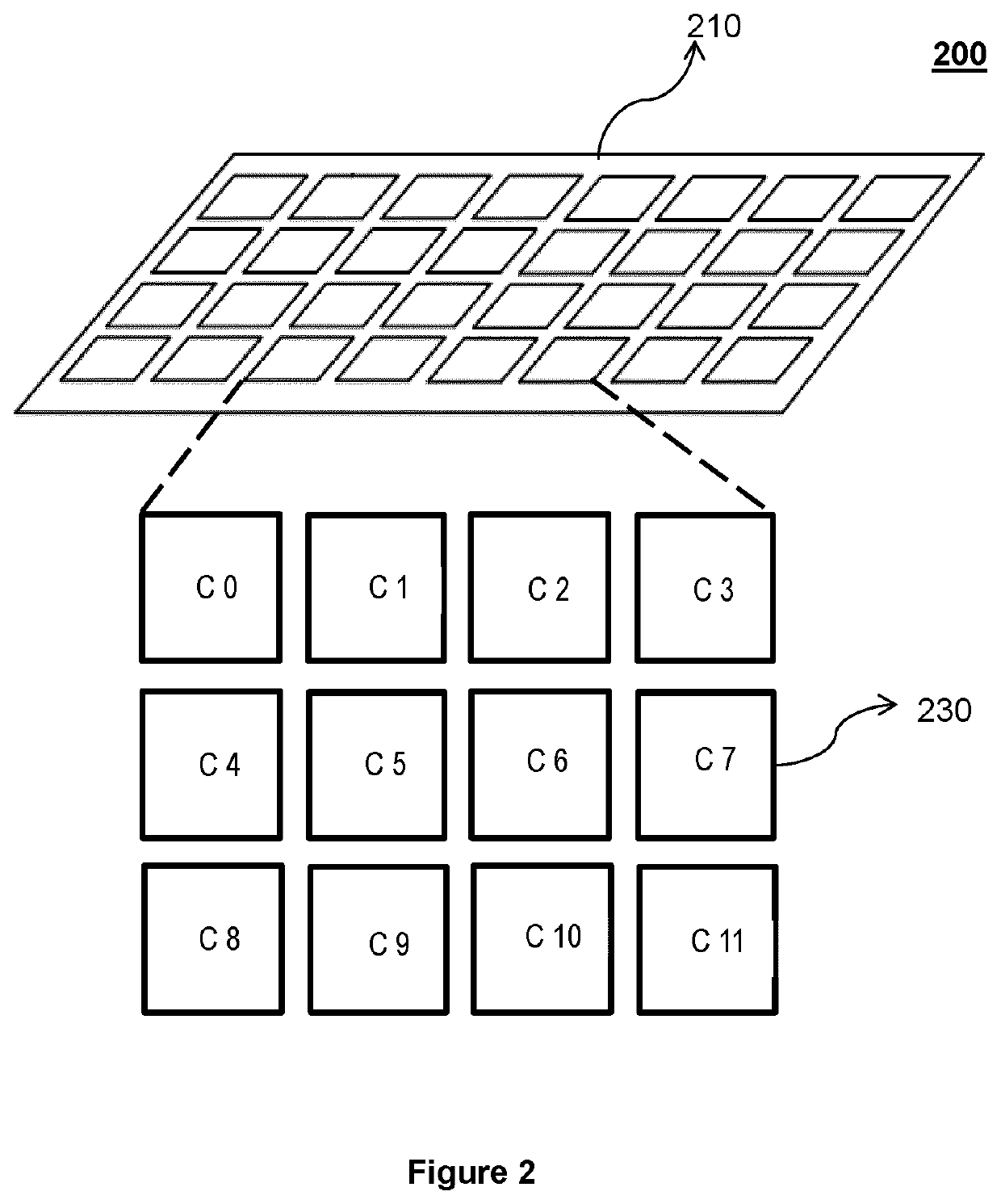
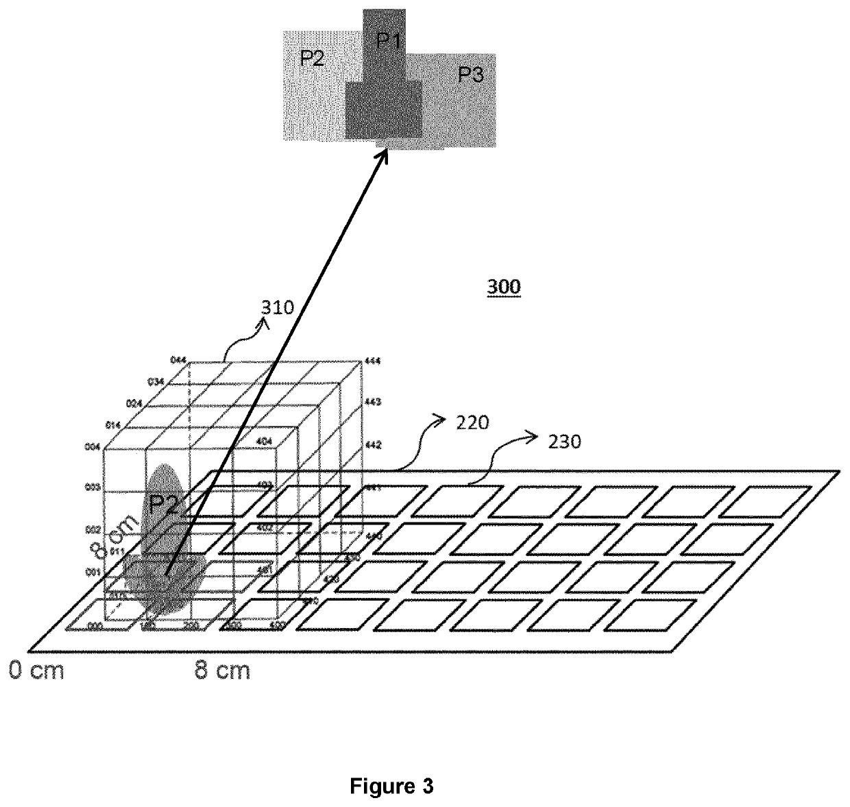
[0012]The apparatus and method of the present disclosure use a phased array antenna, and a processor configured to control the phased array antenna to transmit a wireless signal to the wireless marker, receive a wireless signal transmitted by the wireless marker in response to the transmitted wireless signal, and analyze the wireless signals transmitted and received by the phased array antenna to determine a location of the wireless marker.

[0013]According to some of the example embodiments, the processor is configured to control the phased array antenna to transmit a command to the wireless marker, and receive in response to the transmitted command, a unique digital ID of the wireless marker.

[0014]The processor can be further configured to identify an impedance of the phased array antenna, based on the unique identifier of the located wireless marker and adjust the impedance of the phase array antenna to control the signal strength of the transmitted and the received wireless signal...


PUM


Abstract

The present disclosure provides an apparatus for determining a location of a wireless marker for a tumor, the apparatus comprising: a phased array antenna, and a processor, wherein the processor is configured to control the phased array antenna to transmit a wireless signal to the wireless marker, receive a wireless signal transmitted by the wireless marker in response to the transmitted wireless signal, and analyze the wireless signals transmitted and received by the phased array antenna to determine a location of the wireless marker. The present disclosure also provides a method for determining a location of a wireless marker for a tumor, wherein the method comprises: transmitting, using a phased antenna array, a wireless signal to the wireless marker, receiving, at the phased antenna array, a wireless signal transmitted by the wireless marker in response to the transmitted wireless signal, and analyzing the wireless signals transmitted and received by the phased array antenna to determine a location of the wireless marker.

Description

FIELD OF DISCLOSURE[0001]The present disclosure relates to an apparatus and a method for determining the location of a wireless marker.BACKGROUND OF THE DISCLOSURE[0002]Real-time positioning and tracking a tumor inside a patient's movable tissue (e.g., lung, prostate) is a challenging area in the medical industry and especially in radiation therapy. Various imaging guided approaches have been developed to track a tumor inside patients, for example ultrasound and magnetic resonance. However, these approaches are expensive and the field of view (FoV) is very limited. Moreover, it needs complex real-time imaging reconstruction method to track tumor location due to respiration, organ filling, cardiac conditions, etc.SUMMARY OF THE DISCLOSURE[0003]Recent developments have been made to track an implanted device based on the generated electromagnetic (EM) field, for example biomarkers, close to a patient's tumor to report isocenter location during radiation treatment. While some systems su...

Claims


Application Information

Patent Timeline
Patent Type & Authority Applications(United States)
IPC IPC(8): A61B34/20A61B90/00A61B90/98H01Q3/30
CPCA61B34/20A61B90/39A61B90/98A61B2090/3975A61B2034/2051A61B2034/2072A61B2090/3908H01Q3/30H01Q3/26A61B2090/3983A61N5/1049A61N2005/1051A61B2034/2053A61B2017/00707A61B2017/0092A61B2017/00725
Inventor LIU, RUI
Owner MEDICAL INTELLIGENCE MEDIZINTECHN
Why Eureka
Try Eureka