Linear compressor and control method thereof

Inactive Publication Date: 2005-03-31
SAMSUNG ELECTRONICS CO LTD
View PDF6 Cites 6 Cited by
  • Summary
  • Abstract
  • Description
  • Claims
  • Application Information

AI Technical Summary

Benefits of technology

[0012] Accordingly, it is an aspect of the present invention to provide a linear compressor t

Problems solved by technology

If the sensor circuit of the conventional linear compressor takes the linear property represented by a small angle of the slope like a line “b” due to the external environment, the piston controlled according to a no

Method used


Image

  • Linear compressor and control method thereof
  • Linear compressor and control method thereof
  • Linear compressor and control method thereof

Examples


Embodiment Construction

[0034] Reference will now be made in detail to the embodiments of the present invention, examples of which are illustrated in the accompanying drawings, wherein like reference numerals refer to the like elements throughout. The embodiments are described below to explain the present invention by referring to the figures.

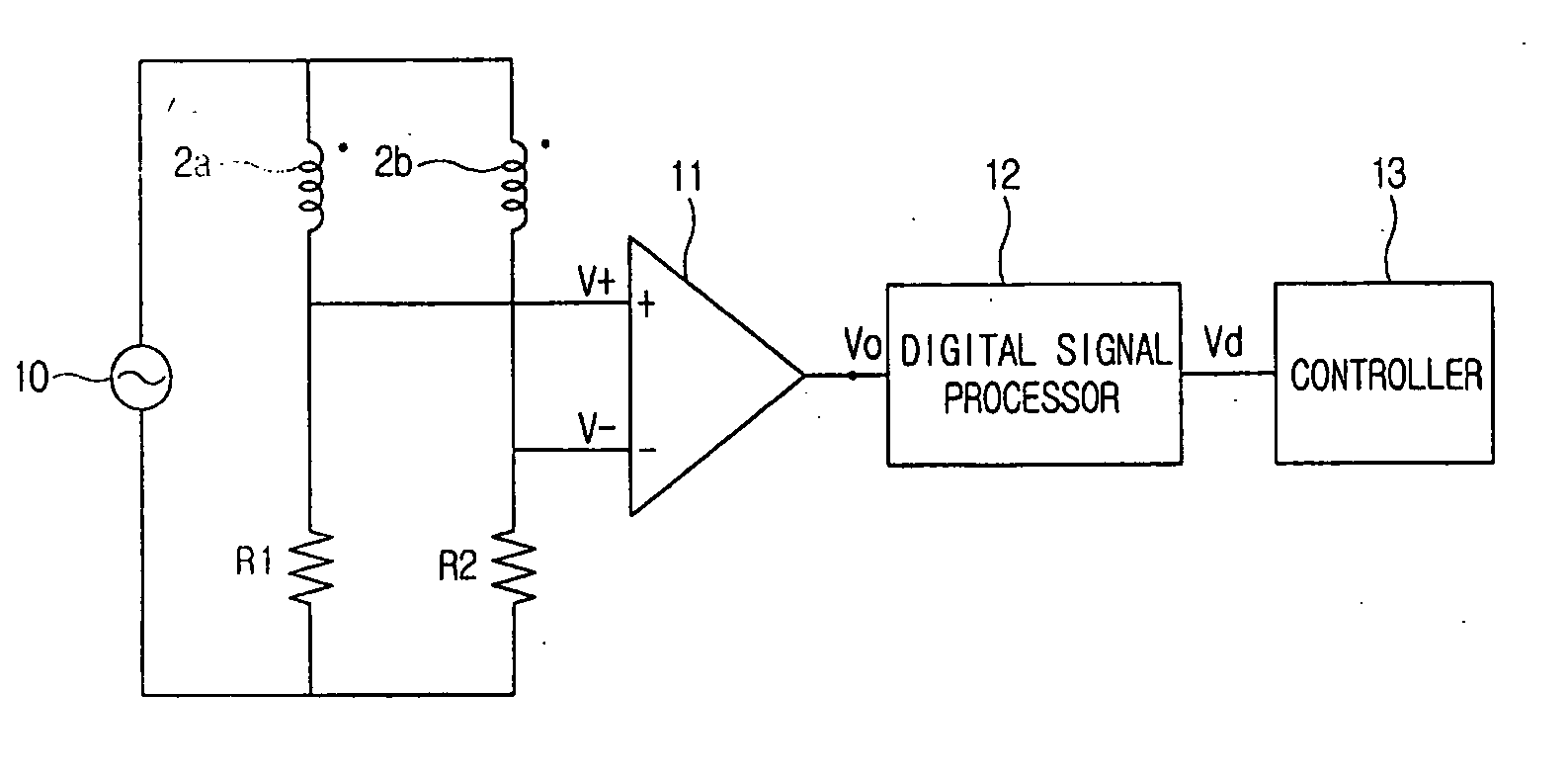
[0035]FIG. 4 is a cross-sectional view of a position detection sensor for a piston of a linear compressor according to an embodiment of the present invention. As illustrated in FIG. 4, a position detection sensor 40 comprises a sensor body 1, a sensor coil 2, a core support 3, and a core 4.

[0036] The sensor body 1 includes a sensor coil 2 inside. The sensor coil 2 comprises a first sensor coil 2a connected in series with a second sensor coil 2b. The first sensor coil 2a and second sensor coil 2b have the same inductance value, size, and number of turns. The core support 3 is made of non-magnetic material that supports the core 4 and is combined to the piston (not sh...


PUM


Abstract

A linear compressor having a core combined to one end of a piston to detect a position of the piston reciprocally moving up and down. A first sensor coil and a second sensor coil detect the position of the core. The core has an upper core having a length shorter than one half of the length of the first sensor coil and a lower core having a length shorter than one half of the length of the second sensor coil in series. A method of controlling the operation of the linear compressor includes timing the upper core and the lower core driven by the piston through a stroke cycle, receiving the time and calculating a top dead center position based on the time or an offset value respectively, and controlling a piston stroke by varying the power driving the linear compressor according to the calculated top dead center or offset value.

Description

CROSS-REFERENCE TO RELATED APPLICATIONS [0001] This application claims the benefit of Korean Patent Application No. 2003-37589, filed Jun. 11, 2003, in the Korean Intellectual Property Office, the disclosure of which is incorporated herein by reference. BACKGROUND OF THE INVENTION [0002] 1. Field of the Invention [0003] The present invention relates to a linear compressor and a control method thereof. [0004] 2. Description of the Related Art [0005] A linear compressor is widely used to compress coolant in a freezing cycle such as a refrigerator, etc. The linear compressor measures the magnitude of a stroke of a piston, and controls an operation of the piston by applying a current to a driving motor of the linear compressor based on an analysis of the measured magnitude of the stroke of the piston. [0006]FIG. 1 is a cross-sectional view of a position detection sensor of a piston of a conventional linear compressor. As illustrated in FIG. 1, the position detection sensor comprises a s...

Claims


Application Information

Patent Timeline
IPC IPC(8): F04B17/04F04B35/04F04B49/06
CPCF04B35/045F04B2203/0402F04B2201/0201F04B17/04
Inventor KIM, HYO-SUK
Owner SAMSUNG ELECTRONICS CO LTD
Why Eureka
Try Eureka