Apparatus and method for automatically compensating for lateral runout

a technology of automatic compensation and lathe, which is applied in the direction of turning machine accessories, portable lathes, manufacturing tools, etc., can solve the problems of disc brake assembly producing at least a degree of lateral runout, individual component defects, and many other problems affecting the automotive industry

Inactive Publication Date: 2006-02-16
BONITA IP
View PDF50 Cites 1 Cited by
  • Summary
  • Abstract
  • Description
  • Claims
  • Application Information

AI Technical Summary

Benefits of technology

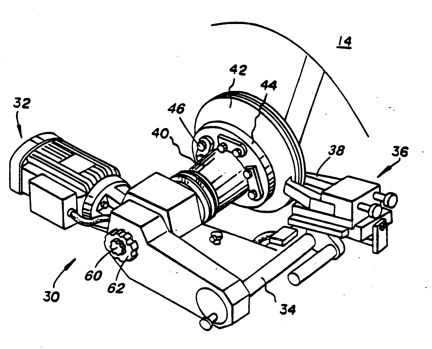
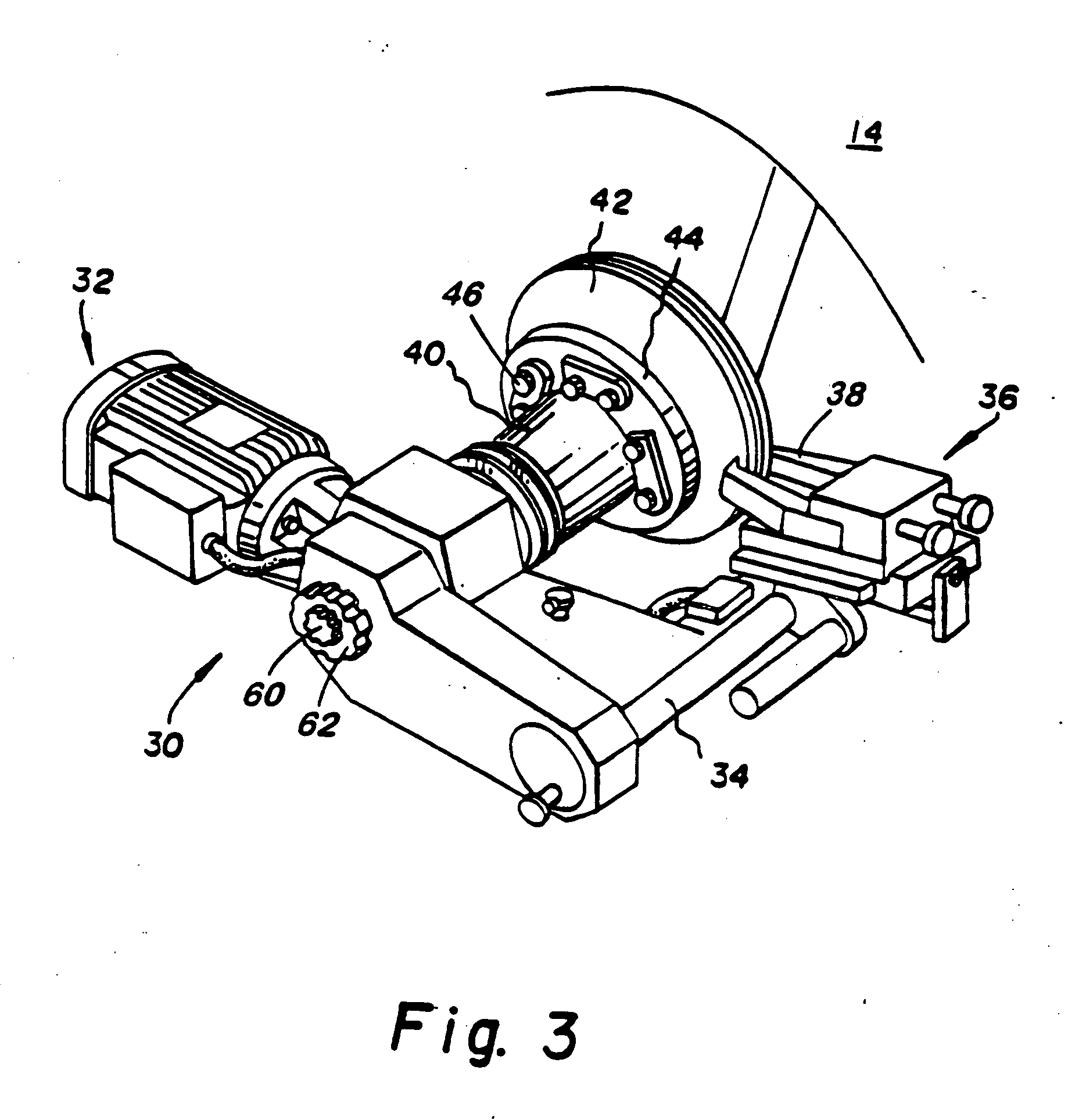
[0024] It is therefore a general object of the invention to provide a novel on-car disc brake lathe system which will obviate or minimize difficulties of the type previously described.
[0025] It is another general object of the invention to provide a novel runout measurement and control system for an on-car disc brake lathe that accurately detects and quantifies the runout of a lathe apparatus with respect to a vehicle hub assembly.

Problems solved by technology

However, several problems have plagued the automotive industry since the inception of disc brakes.
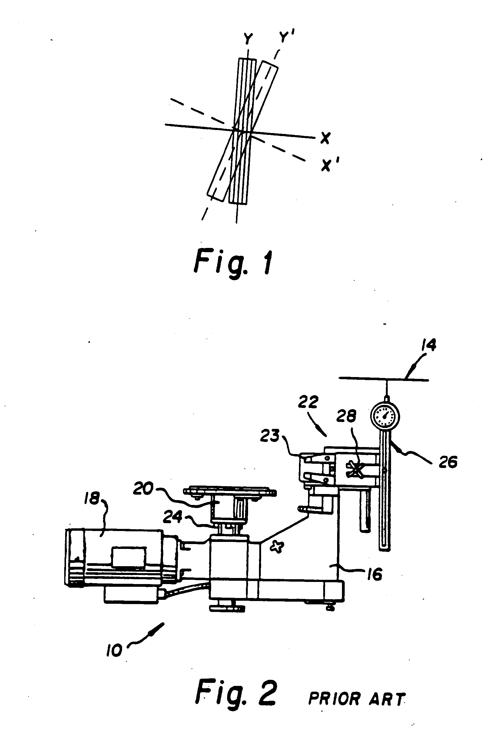
A significant problem in brake systems is usually referred to as “lateral runout.” Generally, lateral runout is the side-to-side movement of the friction surfaces of the rotor as it rotates with the vehicle hub about a spindle axis.
More typically, however, the disc brake assembly will produce at least a degree of lateral runout that deviates from the ideal configuration.
This lateral runout often results from defects in individual components.
An excessive amount of lateral runout in a component or in the assembly (i.e. stacked runout) will generally result in brake noise, pedal pulsation, and a significant reduction in overall brake system efficiency.
Moreover, brake pad wear is uneven and accelerated with the presence of lateral runout.
Bench mounted lathes, for example, that disclosed in U.S. Pat. No. 3,540,165 to Lanham, are inefficient and do not have rotor matching capabilities.
Even if the rotor is mounted to the lathe in a perfectly centered and runout free manner, runout between the rotor and hub is not accounted for in the bench lathe resurfacing operation.
In addition, bench lathes are susceptible to bent shafts which introduce runout into a machined rotor.
Similarly, caliper-mounted lathes, for example, that disclosed in U.S. Pat. No. 4,388,846 to Kopecko et al., have had limited success in compensating for lateral runout, but require time consuming manual operations.
The caliper-mount lathes are wholly unacceptable for many reasons including the lack of a “rigid loop” connection between the driving motor and cutting tool and the inability to assure a perpendicular relationship between the cutting tools and the rotor.
Moreover, the caliper-mount lathes do not have any reliable means for measuring and correcting lateral runout.
This measurement technique is problematic in terms of time, accuracy and ability of automechanics to comfortably use the equipment.
Although the hub mounted on-car brake lathe was a considerable advance in the disc brake lathe industry, its structure and corresponding procedure for compensating for lateral runout of the disc brake assembly has practical limitations.
First, as readily apparent, upon observation of steps (1)-(6) above, the Ekman procedure requires a significant amount of time to determine and adjust for lateral runout of the brake assembly.
Although the specific amount of time necessary will vary based upon operator experience, the procedure time for even the most trained and experience is significant and can substantially increase the cost associated with rotor refinishing to the vehicle owner and the shop.
In general, the prior art systems and procedures are problematic with respect to accuracy in the measuring and adjusting of lateral runout.
Moreover, even if the operator correctly locates and / or relocates the high point of lateral runout, human errors are often introduced during the adjustment process.
For example, selecting the correct screw or screws 24 and applying the precise amount of torque necessary for adjustment is often difficult and imprecise.

Method used


Image

  • Apparatus and method for automatically compensating for lateral runout
  • Apparatus and method for automatically compensating for lateral runout
  • Apparatus and method for automatically compensating for lateral runout

Examples


first embodiment

[0076] A second preferred embodiment incorporates the fundamental features of those disclosed with respect to the first embodiment, but permits adjustment with only one slant disc and the output pivots in one selectable axis only when driven by the slant disc. In the first preferred embodiment, the compensation vector (explained in more detail with reference to FIGS. 11a and 11b) necessary to adjust the angle of the output adaptor 78 could potentially require adjustment of two slant discs. The fixed pivoting axis of the second preferred embodiment eliminates this problem, requiring only one adjustment, potentially reducing the time required for shaft alignment.

[0077] Referring to FIG. 10a, there is shown a cross-sectional view of the automatic alignment coupling or mechanism 120 that occupies the same position of the mechanism 50 of the first embodiment shown in FIG. 4. Input adaptor 122 attaches to the rotating shaft of the lathe machine. Shaft 124 is attached to the input adaptor ...

second embodiment

[0080] Referring now to FIGS. 11a and 11b, there is shown a schematic depicting the relationship between the compensation vector, compensation angle, and pivot axis contemplated by the alignment device of the present invention. Generally, two parameters are of importance when aligning the rotating shafts of the lathe and brake hub. The first parameter referred to as the “compensation vector” is defined by the a rotation position at which the lateral runout deflection of the brake lathe is the greatest. The second parameter referred to as the “compensation angle” is defined by the angle that the input adaptor and the output adaptor must assume in relation to each other in order to compensate for this lateral runout. In the second embodiment, the compensation vector and the compensation angle can be adjusted separately as shown in FIG. 10a.

[0081] However, in the first and third (described below) embodiments, the compensation vector is adjusted by “stopping” simultaneously the input d...


PUM

PropertyMeasurementUnit
timeaaaaaaaaaa
angleaaaaaaaaaa
face anglesaaaaaaaaaa

Abstract

An apparatus and method for automatically compensating for the lateral runout between an on-car lathe apparatus and a vehicle hub axis including one or more stop discs that rotate with the drive shaft of the lathe and that can be selectively stopped from rotating with the shaft by a stop mechanism. In response to such stopping, one or more adjustment discs are caused to rotate in order to adjust the relative position of the axis of the lathe with respect to the axis of the disc brake assembly. In this manner, the system compensates for and corrects lateral runout that exists between two concentrically attached rotating shafts.

Description

BACKGROUND OF THE INVENTION [0001] This invention relates to an improved on-car brake lathe apparatus. More specifically, this invention relates to an apparatus and method for automatically compensating for the lateral runout of a lathe apparatus with respect to a vehicle hub. The invention further includes a novel runout measurement and control system that describes the runout of a disc brake assembly and directs a corrective signal to an automated control system for adjustment in order to effectively compensate of lateral runout. The novel runout apparatus and method may also be advantageously utilized in other practical applications in order to align two concentrically attached rotating shafts. [0002] A brake system is one of the primary safety features in every road vehicle. The ability to quickly decelerate and bring a vehicle to a controlled stop is always critical to the safety of the vehicle occupants and those in the immediate vicinity. In this, a vehicle braking system is ...

Claims


Application Information

Patent Timeline
Patent Type & Authority Applications(United States)
IPC IPC(8): B23B5/04B23Q15/22
CPCB23B5/04B23B2235/045B23B2235/21Y10T82/2571Y10T82/2535Y10T82/21Y10T82/10Y10T82/2502Y10T82/2574
Inventor NEWELL, HAROLDWIGGINS, JOHN
Owner BONITA IP
Why Eureka
Try Eureka