Radiation detecting device and method for manufacturing radiation detecting device

a radiation detection and radiation detection technology, applied in the direction of x/gamma/cosmic radiation measurement, radioation controlled devices, instruments, etc., can solve the problems of easy intrusion and deterioration of durability of radiation detection devices, so as to prevent intrusion and enhance durability performance of radiation detection devices

Inactive Publication Date: 2016-12-29
FUJIFILM CORP
View PDF1 Cites 8 Cited by
  • Summary
  • Abstract
  • Description
  • Claims
  • Application Information

AI Technical Summary

Benefits of technology

[0018]According to the above-described aspects of the invention, it is possible to provide a radiation detecting device and a method for manufacturing the radiation detecting device capable of preventing intrusion of moisture and enhancing durability performance of the radiation detecting device.

Problems solved by technology

In such a case, when the thickness of the adhesive layer increases, there is a concern that moisture may easily intrude and thus durability of the radiation detecting device may deteriorate.

Method used


Image

  • Radiation detecting device and method for manufacturing radiation detecting device
  • Radiation detecting device and method for manufacturing radiation detecting device
  • Radiation detecting device and method for manufacturing radiation detecting device

Examples


first embodiment

[0031]A radiation detecting device of a first embodiment has a function of receiving radiation passed though an object and outputting image information indicating a radiographic image of the object. The radiation detecting device includes a photoelectric conversion substrate and a phosphor layer which is a scintillator that receives radiation and emits light.

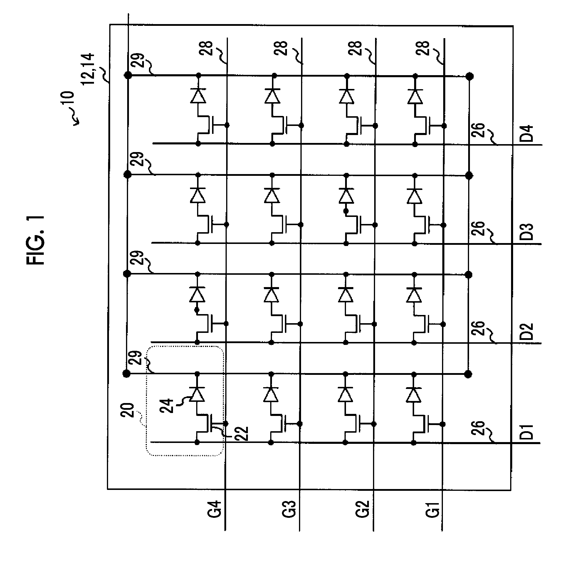
[0032]FIG. 1 shows an example of a specific configuration of the radiation detecting device of this embodiment.

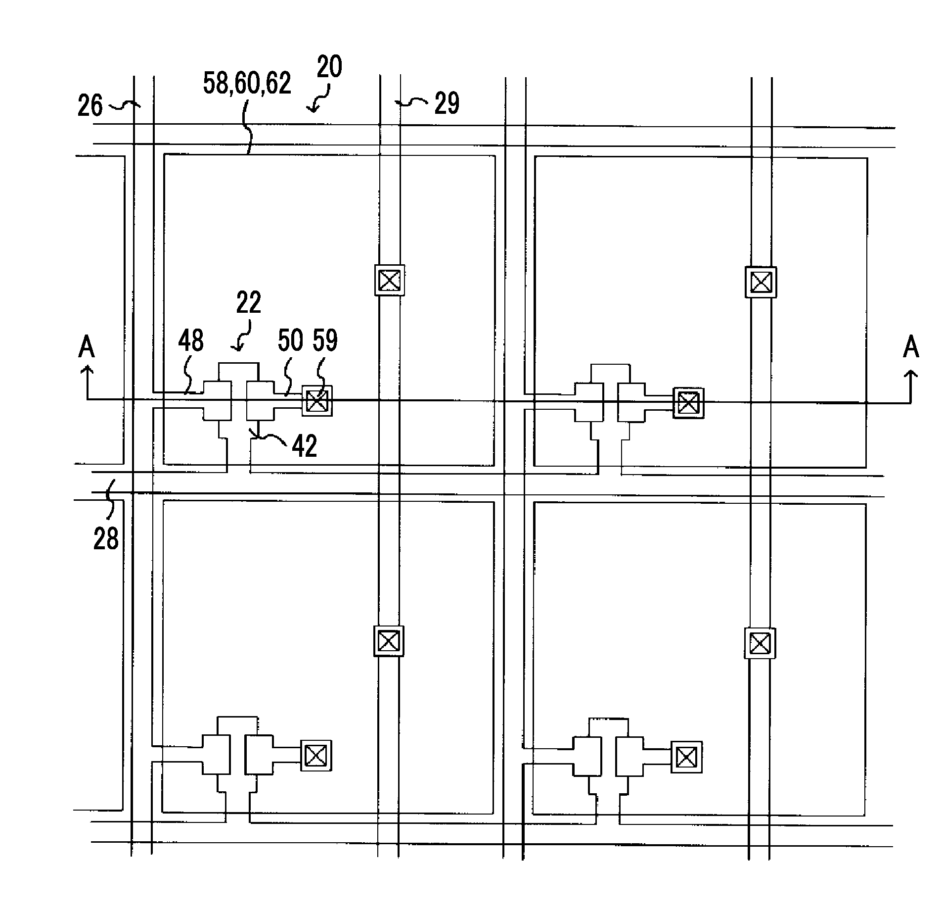
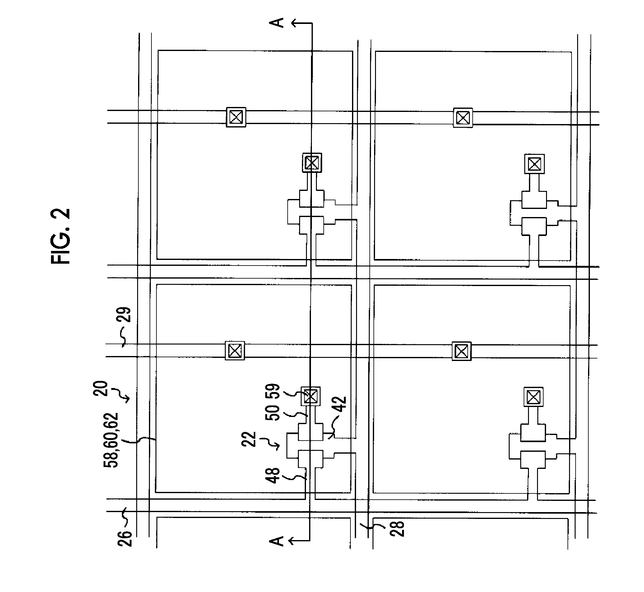
[0033]A radiation detecting device 10 comprises a photoelectric conversion substrate 12, and the photoelectric conversion substrate 12 includes a thin film transistor (TFT) substrate 14 on which plural pixels 20 are formed. As shown in FIG. 1, the TFT substrate 14 of the photoelectric conversion substrate 12 includes the plural pixels 20 that include a sensor unit 24 and a switch element 22. The sensor unit 24 receives light generated in a phosphor layer to generate electric charges. The switch element 22 reads the elec...

second embodiment

[0089]Next, a second embodiment will be described. In the radiation detecting device 10 of this embodiment, since the groove portion 80 is different from that of the first embodiment, the groove portion 80 will be described. The same reference numerals are given to the same portions as in the radiation detecting device 10 according to the first embodiment, and detailed description thereof will not be repeated.

[0090]FIG. 8 is a sectional view corresponding to a B-B section in FIG. 4 in the first embodiment. In the radiation detecting device 10 of this embodiment shown in FIG. 8, the groove portion 80 passes through the surface organic film 70, the second flattening film 64, and the first flattening film 54, and reaches the surface of the TFT protective film layer 52. Further, the surface organic film 70 is formed to cover the top of the second flattening film 64 and an inner side wall of the groove portion 80.

[0091]When forming the groove portion 80 in this way, in the surface organi...

third embodiment

[0094]Next, a third embodiment will be described. In the radiation detecting device 10 of this embodiment, since the groove portion 80 is different from that of each of the above-described embodiments, the groove portion 80 will be described. The same reference numerals are given to the same portions as in the radiation detecting device 10 according to the first embodiment, and detailed description thereof will not be repeated.

[0095]FIG. 9 is a sectional view corresponding to the B-B section in FIG. 4 according to the first embodiment. In the radiation detecting device 10 of this embodiment shown in FIG. 9, the groove portion 80 passes through the surface organic film 70, the second flattening film 64, and the first flattening film 54, and reaches the surface of the TFT protective film layer 52.

[0096]Further, in the radiation detecting device 10 of this embodiment, a configuration outside the sealing region 92 of the photoelectric conversion substrate 12, more specifically, a config...


PUM


Abstract

In a radiation detecting device, a groove portion is provided in a sealing region on a photoelectric conversion substrate. The groove portion is provided in the vicinity of a phosphor layer formed on the photoelectric conversion substrate or along an outer peripheral side thereof. A moisture-proof protective layer is provided to cover the phosphor layer and the sealing region through an adhesive layer. The adhesive layer is cured when in a flowable state to function as an adhesive. In a case where the moisture-proof protective layer is adhered, the adhesive layer enters a flowable state, and thus, the adhesive layer flows into the groove portion and fills at least a part of the inside of the groove portion.

Description

CROSS-REFERENCE TO RELATED APPLICATIONS[0001]This application is a continuation application of International Application No. PCT / JP2015 / 058599, filed Mar. 20, 2015, the disclosure of which is incorporated herein by reference in its entirety. Further, this application claims priority from Japanese Patent Application No. 2014-070543, filed Mar. 28, 2014, the disclosure of which is incorporated herein by reference in its entirety.BACKGROUND OF THE INVENTION[0002]1. Field of the Invention[0003]The present invention relates to a radiation detecting device and a method for manufacturing the radiation detecting device.[0004]2. Description of the Related Art[0005]In the related art, a radiation imaging device that performs radiation imaging for medical diagnosis is known. In such a radiation imaging device, a radiation detecting device for detecting radiation passed through an object to generate a radiographic image is used.[0006]As the radiation detecting device, there is a radiation detec...

Claims


Application Information

Patent Timeline
Patent Type & Authority Applications(United States)
IPC IPC(8): H01L27/146
CPCH01L27/14663H01L27/14685H01L27/1462G01T1/202
Inventor ITO, TAKAAKI
Owner FUJIFILM CORP
Why Eureka
Try Eureka