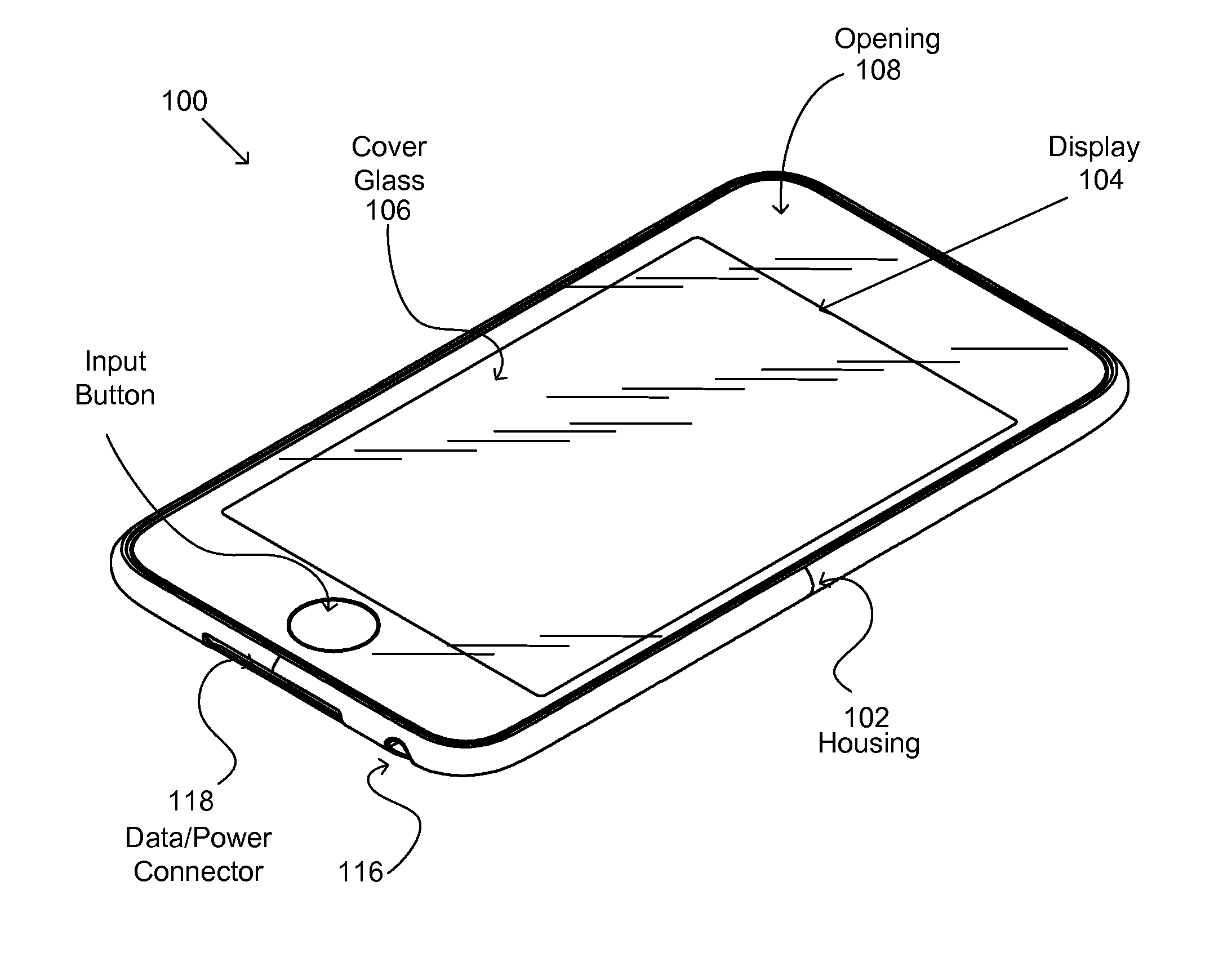
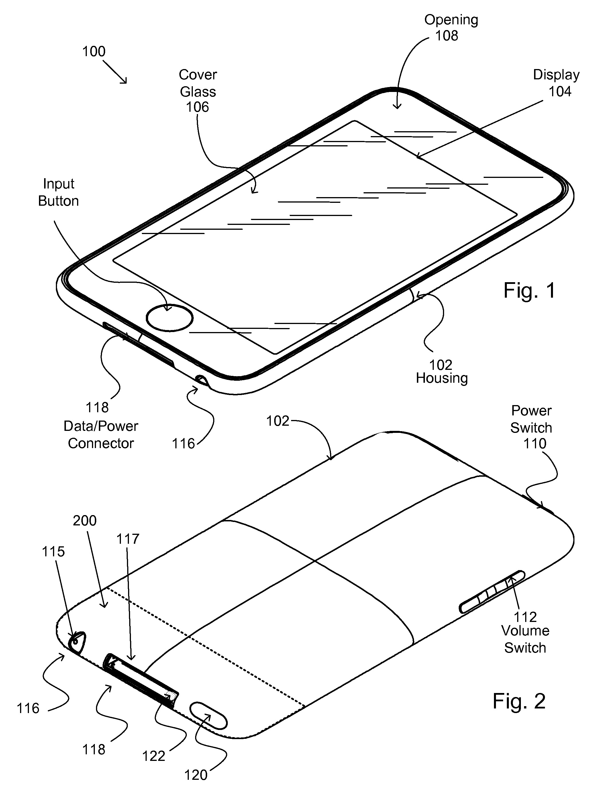
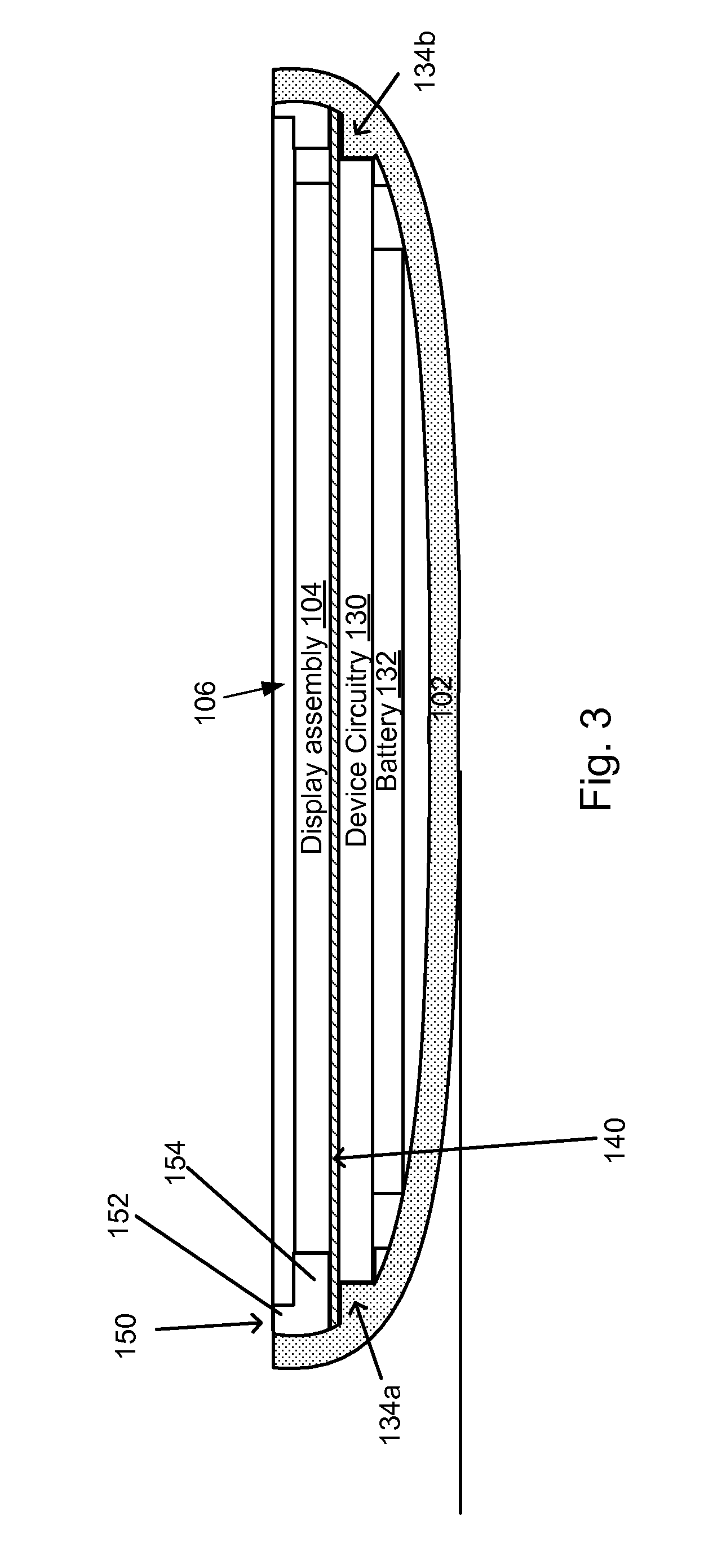
Heat sealed connector assembly

a connector and sealing technology, applied in the direction of coupling device connections, paper/cardboard containers, identification means, etc., can solve the problems of user dissatisfaction, damage to internal parts, and difficulty in shape, so as to prevent moisture intrusion

Inactive Publication Date: 2014-01-21
APPLE INC
View PDF26 Cites 7 Cited by
  • Summary
  • Abstract
  • Description
  • Claims
  • Application Information

AI Technical Summary

Benefits of technology

[0010]In one aspect, a metal housing is laser welded to the bracket using at least one exposed dimple as a laser target. In this way, the sealing tape prevents moisture passing from the external environment via the electrical contacts to the interior of the device housing thereby protecting the operational components from moisture related contamination.
[0011]A method of preventing moisture intrusion from an external environment into an interior of an electronic device having housing with an opening to the external environment is performed by carrying out the following operations. Providing a heat sealed electrical connector assembly. In the described embodiment, the heat sealed electrical connector assembly includes a plurality of electrical contacts at least a portion of which are exposed to the external environment where each of the electrical contacts are sealed to prevent the transport of moisture from the external environment to the interior of the electronic device. Placing the heat sealed electrical connector assembly within the opening and securing the heat sealed electrical connector assembly to the opening. In this way, the heat sealed electrical connector assembly substantially prevents moisture from passing from the exterior environment to the interior of the electronic device.

Problems solved by technology

One design challenge associated with the small form factor electronic device is the design of the enclosures used to house the various internal components.
This design challenge generally arises from a number conflicting design goals that includes the desirability of making the enclosure lighter and thinner, the desirability of making the enclosure stronger and making the enclosure more esthetically pleasing.
Unfortunately, increased weight can lead to user dissatisfaction, and bowing can damage the internal parts.
This shape can be challenging when attempting to provide openings used to accommodate input / output devices such as connectors, audio ports, etc.

Method used


Image

  • Heat sealed connector assembly
  • Heat sealed connector assembly
  • Heat sealed connector assembly

Examples


Embodiment Construction

[0007]A method for heat sealing an electrical connector assembly is described. In the embodiment, the electrical connector assembly includes a plurality of electrical contacts each having a flat pad portion and an upraised portion in the form of a dimple, at least one window bracket arranged to engage a corresponding latch on a plug when the plug is inserted and engaged with the electrical connector assembly. The method can be carried out by performing at least the following operations. Providing the connector assembly in component accessible state, providing sealing tape, the sealing tape comprising a thin film impregnated with a heat sensitive adhesive, overlaying the housing and the flat pad portion of at least some of the electrical contacts with the sealing tape leaving at least some of the dimples substantially exposed, applying an amount of heat to the sealing tape, the amount of heat sufficient to liquefy the heat sensitive adhesive such that the liquefied adhesive flows ove...


PUM

PropertyMeasurementUnit
heat sensitiveaaaaaaaaaa
spring forceaaaaaaaaaa
flexibleaaaaaaaaaa

Abstract

Heat sealing a connector assembly can be performed by providing connector assembly in component accessible state, overlaying sealing tape on electrical contacts and housing, sealing tape being impregnated with heat sensitive adhesive, the overlaying leaving the dimples exposed, and sealing the connector assembly by applying heat to heat sensitive sealing tape.

Description

CROSS REFERENCE TO RELATED APPLICATIONS[0001]This U.S. patent application claims priority under 35 U.S.C. 119(e) to U.S. Provisional Application entitled “Heat Sealed Connector Assembly” by Jol having Application Ser. No. 61 / 378,843 and filed Aug. 31, 2010 and is incorporated by reference in its entirety for all purposes.TECHNICAL FIELD[0002]The described embodiments relate generally to small form factor electronic devices. More particularly, providing grounding support for a connector is described.DESCRIPTION OF THE RELATED ART[0003]The outward appearance of a small form factor electronic device, including its design and its heft can be important factors in determining a user's overall appreciation of the product. For example, the outward appearance and perceived quality of the device functionality can contribute to the overall impression that the user has of the small form factor electronic device. At the same time, the assembly of the small form factor electronic device is also a...

Claims


Application Information

Patent Timeline
Patent Type & Authority Patents(United States)
IPC IPC(8): H01R13/648B31B50/64
CPCH01R24/78H01R13/504H01R43/005H01R13/6594H01R13/6582H01R24/60H01R13/187H01R43/0221G09F9/35H01R13/5216H01R13/6273H01R12/722H01R4/4809H01R2107/00H01R13/2414H01R13/5202Y10T29/49117Y10T156/10
Inventor JOL, ERIC, S.
Owner APPLE INC
Why Eureka
Try Eureka