Electro-optical device and electronic apparatus

Active Publication Date: 2014-07-31
138 EAST LCD ADVANCEMENTS LTD
View PDF1 Cites 6 Cited by
  • Summary
  • Abstract
  • Description
  • Claims
  • Application Information

AI Technical Summary

Benefits of technology

[0007]An advantage of some aspects of the invention is provision of an electro-optical device that includes a seal member having an improved compositi

Problems solved by technology

In case that moisture intrudes from outside into the electro-optical device through the seal member, the electro-optical material is prone to be degraded.
Further, in the electro-optical devices according to JP-A-6-123882 and JPA-2009-80396, when the silica gel micropowder or the porous silicon oxide is saturated with moisture, the hygroscopic effect is no longer expected.
Furthermore, in the case of employing a filler as additive to the seal member as disclosed in JP-A-6-123882

Method used


Image

  • Electro-optical device and electronic apparatus
  • Electro-optical device and electronic apparatus
  • Electro-optical device and electronic apparatus

Examples


Example

First Embodiment

General Configuration

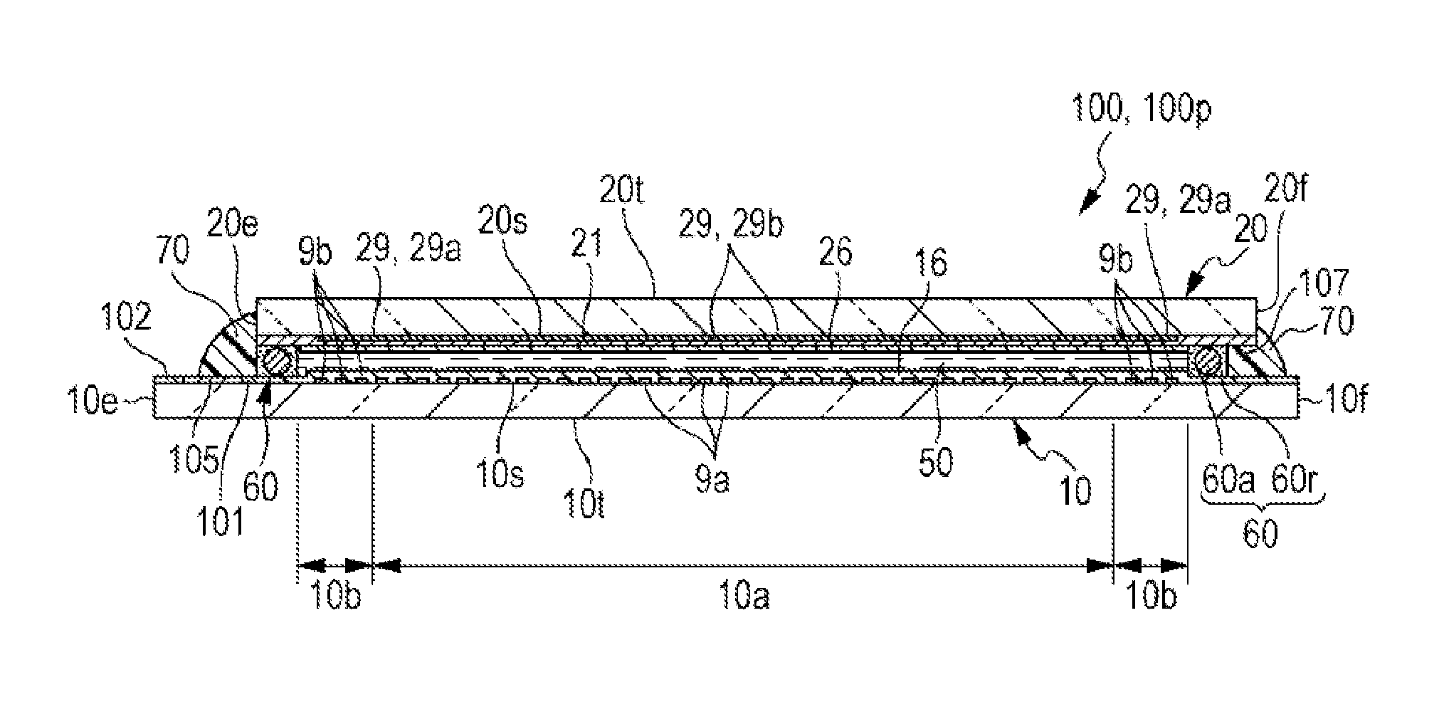
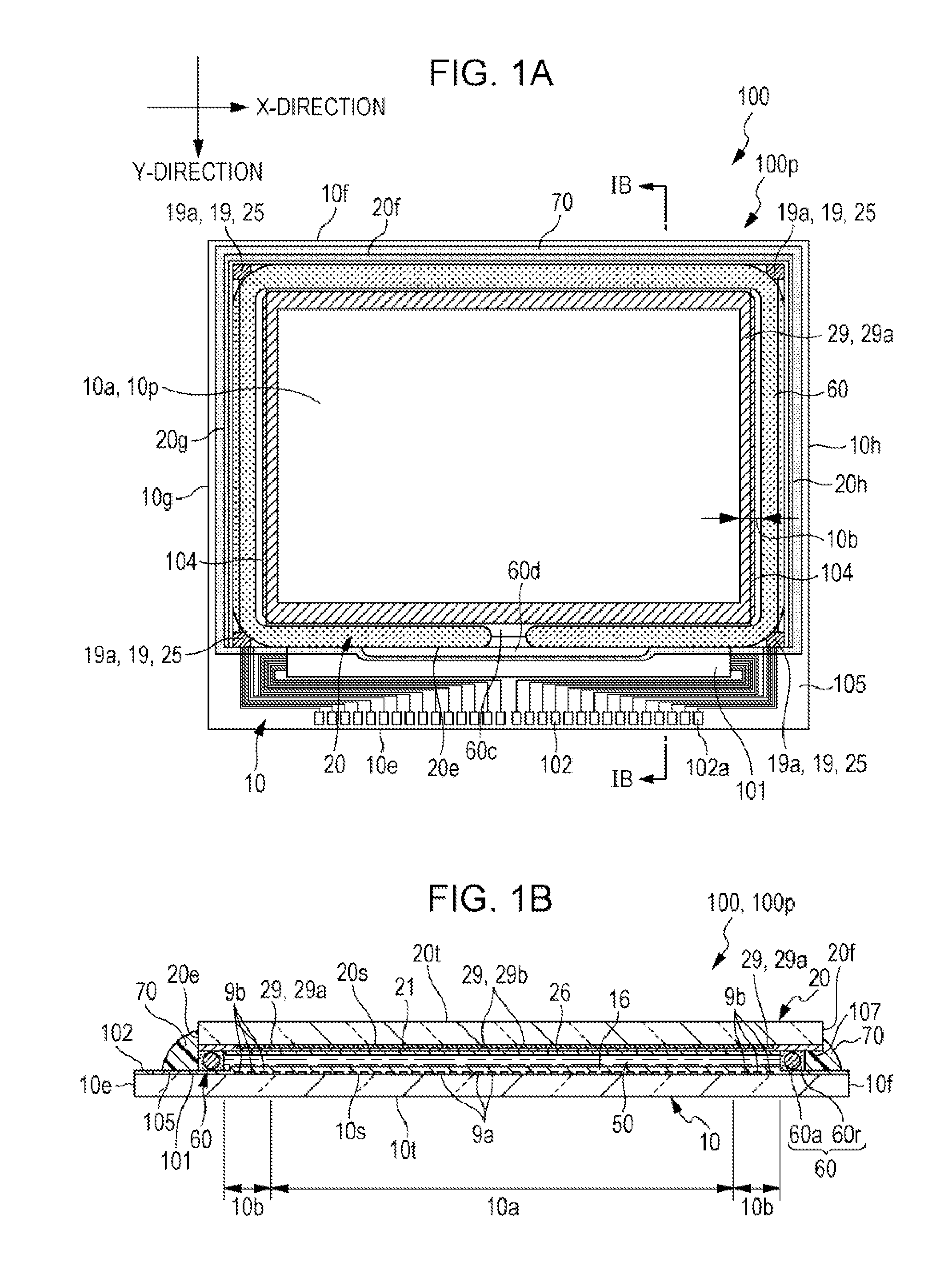
[0023]FIGS. 1A and 1B illustrate a liquid crystal panel of the electro-optical device according to a first embodiment of the invention. FIG. 1A is a plan view of the liquid crystal panel and components thereof seen from the side of a counter substrate, and FIG. 1B is a cross-sectional view taken along a line IB-IB in FIG. 1A.

[0024]The electro-optical device 100 shown in FIGS. 1A and 1B is a liquid crystal device, and includes a liquid crystal panel 100p. The liquid crystal panel 100p includes a first substrate 10 (element substrate) and a second substrate 20 (counter substrate) bonded together with a predetermined gap therebetween by a first seal member 60. The first seal member 60 is provided in a frame shape along the outer periphery of the second substrate 20. The first seal member 60 contains an adhesive 60r composed of a photocuring resin, a thermosetting resin, or the like, and a spacer 60a formed of glass fiber or glass beads dispersed in ...

Example

Second Embodiment

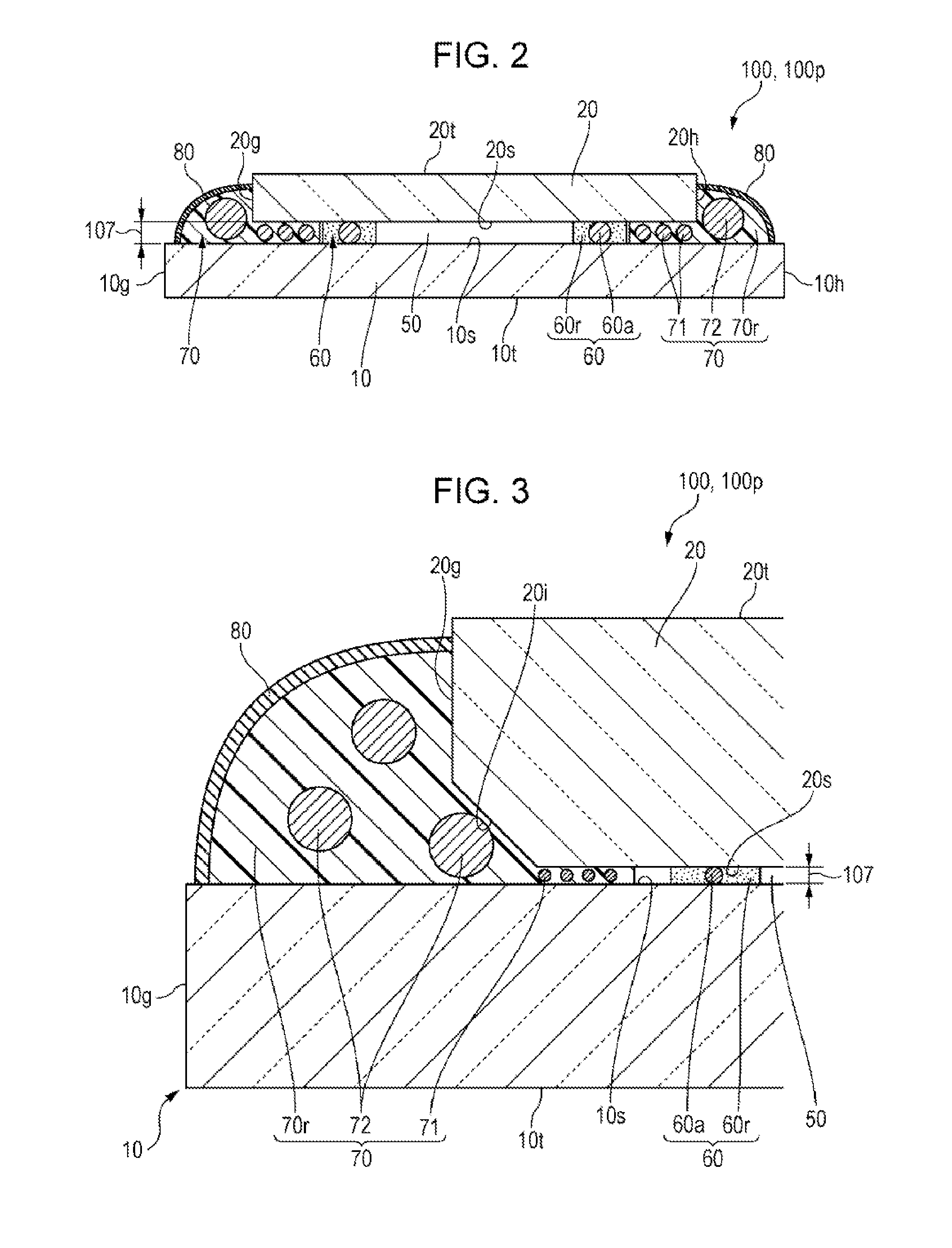
[0052]FIG. 3 is a schematic cross-sectional view of the second seal member 70 provided in the electro-optical device 100 according to a second embodiment of the invention. The basic configuration of this embodiment is generally the same as that of the first embodiment, and therefore the same constituents will be given the same numeral and the description thereof will not be repeated. The following description will focus on a region in the vicinity of the side face 20g of the second substrate 20.

[0053]As shown in FIG. 3, in the electro-optical device 100 according to this embodiment the first seal member 60 serves to bond the first substrate 10 and the second substrate 20 together and to seal the electro-optical material 50, as in the first embodiment. In addition, the second seal member 70 is provided around the entire periphery of the first seal member 60, so as to cover the outer face of the first seal member 60. In this embodiment, further, the insulative inorgan...

Example

Third Embodiment

[0055]FIG. 4 is a schematic cross-sectional view of the second seal member 70 provided in the electro-optical device 100 according to a third embodiment of the invention. The basic configuration of this embodiment is generally the same as that of the first embodiment, and therefore the same constituents will be given the same numeral and the description thereof will not be repeated. The following description will focus on a region in the vicinity of the side face 20g of the second substrate 20.

[0056]In the foregoing embodiments the plurality of second particles 72 in the second seal member 70 have the same diameter, however in this embodiment the second particles 72a, 72b of different diameters are employed as shown in FIG. 4. Between the second particles 72a and 72b, the second particles 72a are smaller in diameter than the second particles 72b, and the diameters of both of the second particles 72a and 72b are larger than the diameters of the first particles 71, the...


PUM


Abstract

In an electro-optical device, an electro-optical material is doubly sealed with a first seal member and a second seal member. In the second seal member, first particles are located in a gap between a first substrate and a second substrate, and second particles are located outside of the gap between the first substrate and the second substrate, so as to cover the opening of the gap.

Description

BACKGROUND[0001]1. Technical Field[0002]The present invention relates to an electro-optical device including an electro-optical material interposed between a first substrate and a second substrate, and an electronic apparatus incorporated with such an electro-optical device.[0003]2. Related Art[0004]Electro-optical devices such as a liquid crystal device generally include a first substrate and a second substrate opposed to each other and bonded together via a seal member, and an electro-optical material including a liquid crystal material located in a space surrounded by the seal member between the first substrate and the second substrate. In case that moisture intrudes from outside into the electro-optical device through the seal member, the electro-optical material is prone to be degraded.[0005]Accordingly, for example JP-A-2009-163082, JP-A-2010-26307, JP-A-6-123882, and JP-A-2009-80396 propose providing a second seal member formed of a resin-based material or a rubber-based mate...

Claims


Application Information

Patent Timeline
IPC IPC(8): G02F1/1339
CPCG02F1/1339
Inventor SHINOHARA, TAKASHI
Owner 138 EAST LCD ADVANCEMENTS LTD
Why Eureka
Try Eureka