

Cable connector assembly having improved metal shell
- Summary
- Abstract
- Description
- Claims
- Application Information
AI Technical Summary
Benefits of technology
Problems solved by technology
Method used
Image

Examples
Embodiment Construction
[0016]Reference will now be made in detail to a preferred embodiment of the present invention.
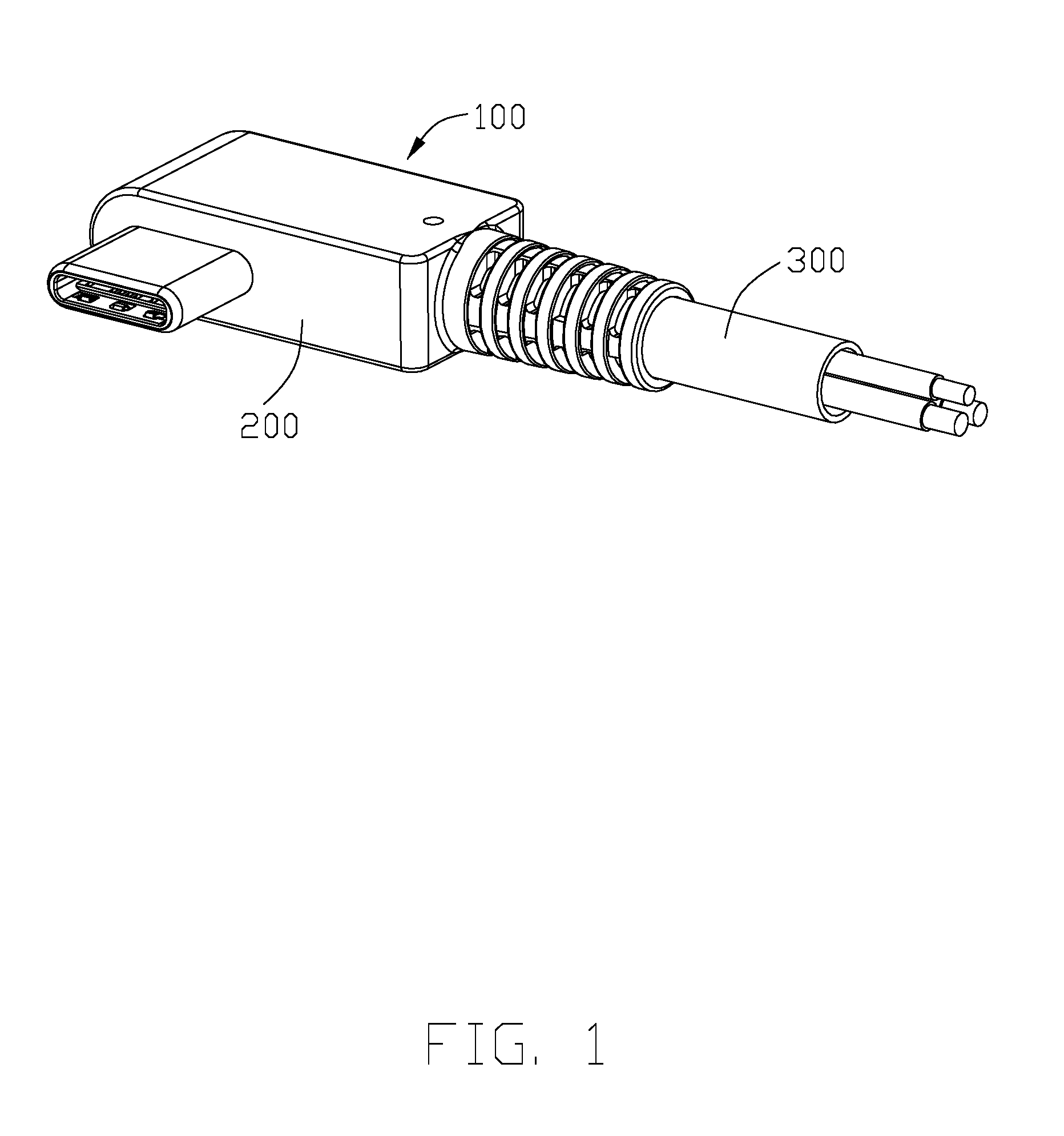
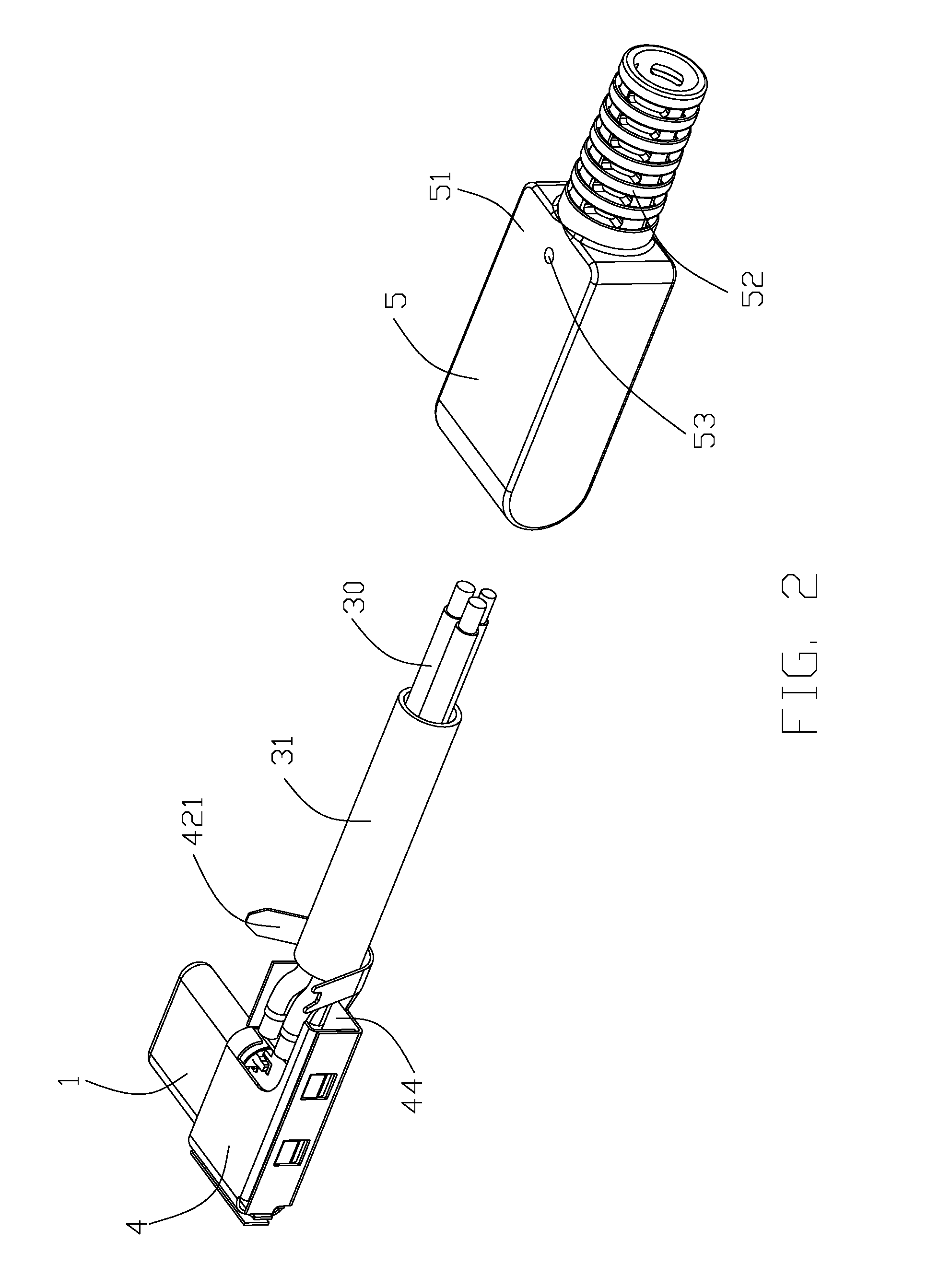
[0017]Referring to FIGS. 1 to 4, a cable connector assembly 100 adapted for being mating with a mating connector, comprises a connector 200, and a cable 300 connected with the connector 200. The connector 200 comprises a mating member 1, a printed circuit board 2 electrically connected with the mating member 1, and a metal shell 4 disposed at an outer side of the mating member 1 and the cable 300, and an outer shell 5 enclosing the metal shell 4. The printed circuit board 2 is received in the metal shell 4.
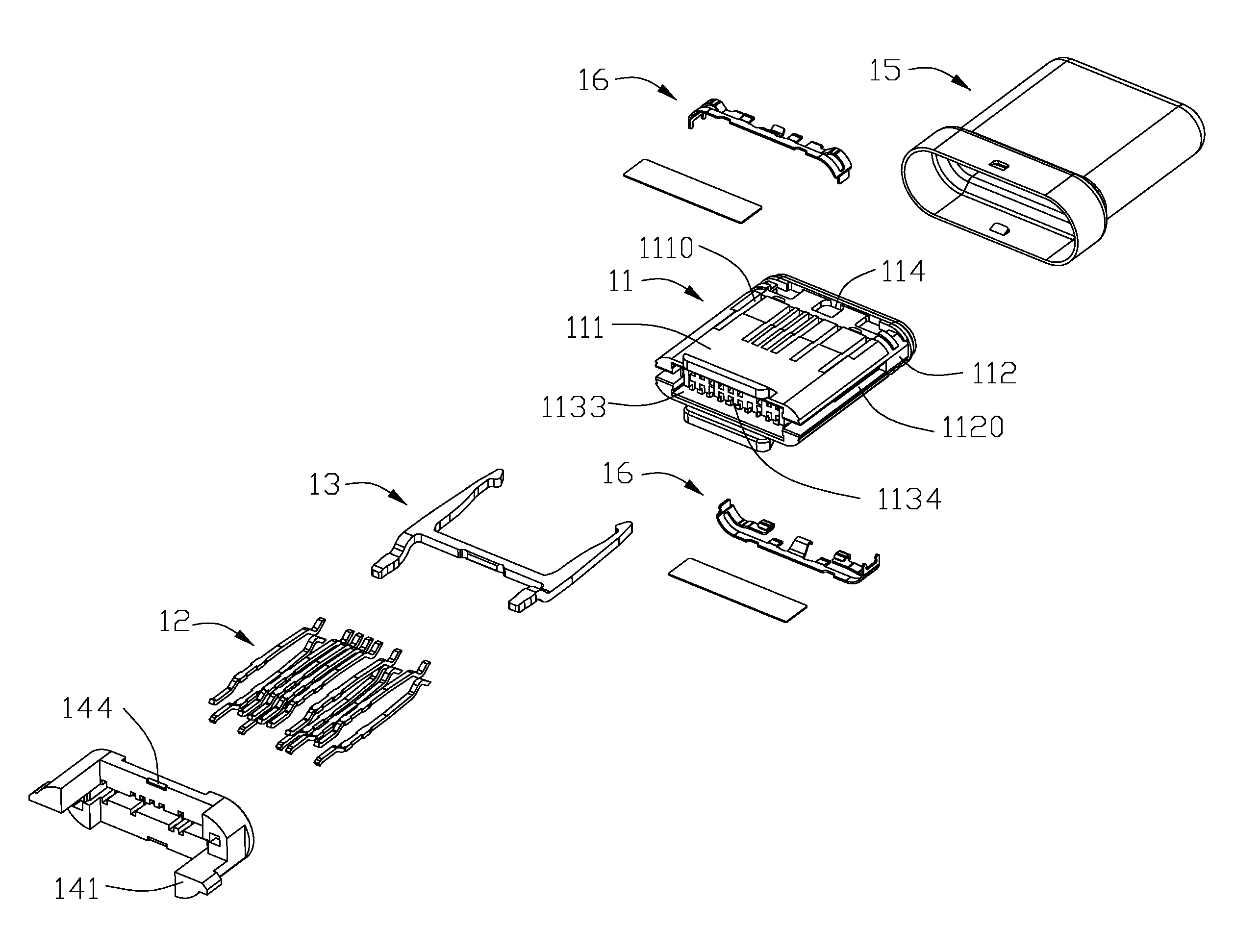
[0018]Referring to FIGS. 7 and 8, the mating member 1 comprises an insulative housing 11, a plurality of contacts 12 arranged in two rows and spaced apart from each other in a vertical direction, a latch 13 disposed between the two rows of contacts 12 for latching with the mating connector, an insulative member 14 assembled on a rear end of the insulative housing 11, a mating shell 15 cov...
PUM
 Abstract
Description
Claims
Application Information