Vacuum hose coupling with quick lock feature

Active Publication Date: 2017-01-05
BLUE LEAF I P
View PDF7 Cites 3 Cited by
  • Summary
  • Abstract
  • Description
  • Claims
  • Application Information

AI Technical Summary

Benefits of technology

The present invention has the advantage of being able to quickly unlock the coupling from the metering device by sliding the locking ring into the unlocked position. Additionally, the locking mechanism can be produced relatively cheaply.

Problems solved by technology

The coupling can be held on to the port with a friction fit, but such a fit is prone to becoming disconnected as the row unit articulates up and down through the field.
Further, the friction fit can make it difficult to unlock the hose from the metering device.

Method used


Image

  • Vacuum hose coupling with quick lock feature
  • Vacuum hose coupling with quick lock feature
  • Vacuum hose coupling with quick lock feature

Examples


Embodiment Construction

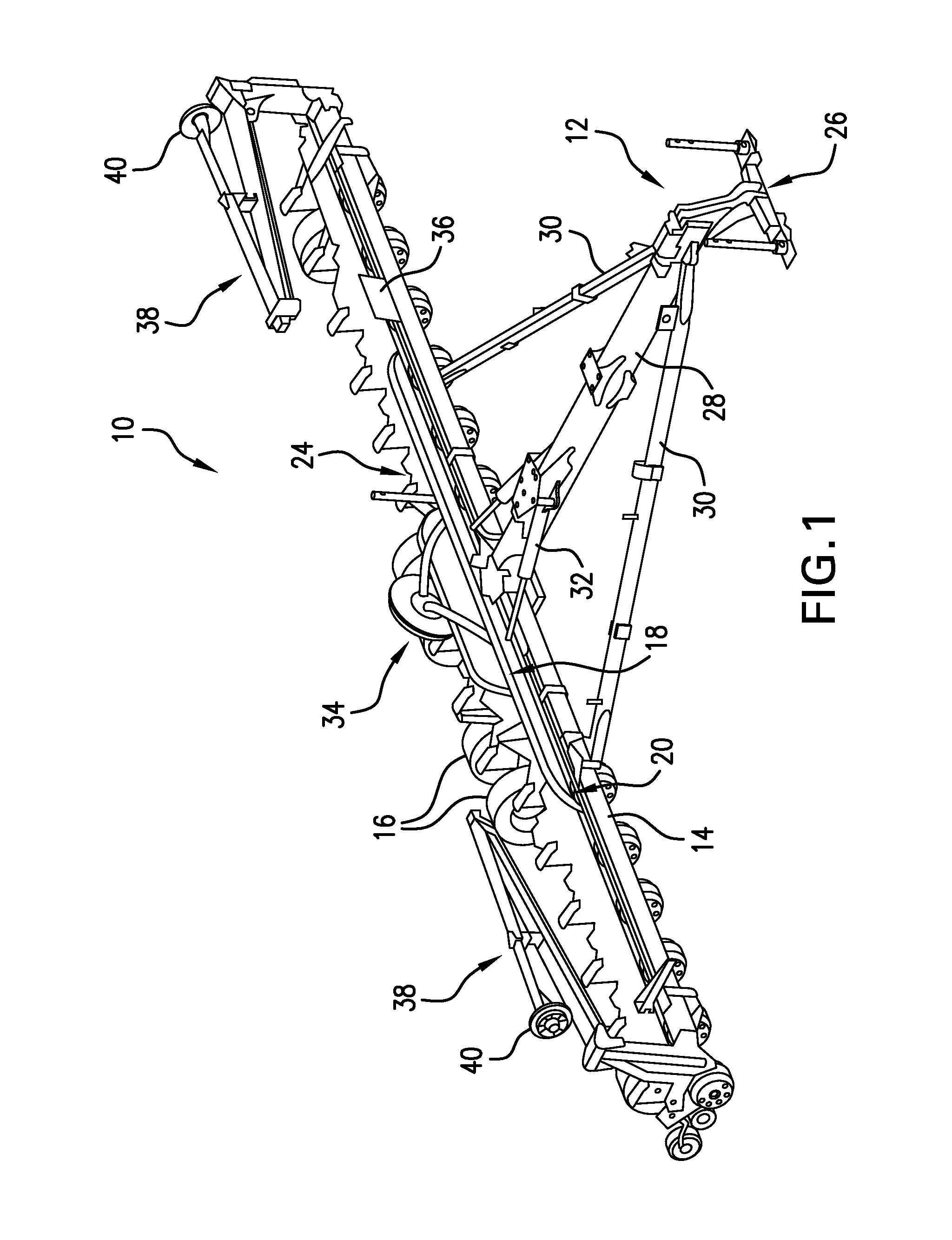
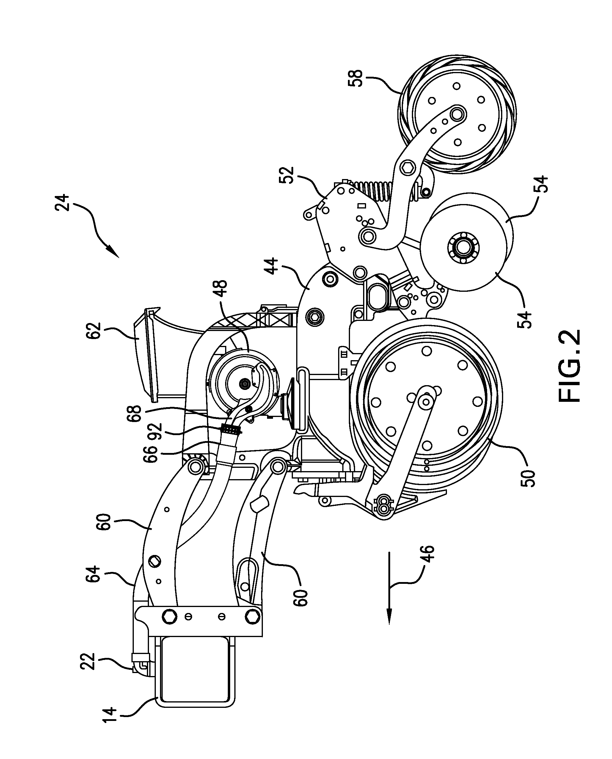
[0029]Referring now to the drawings, and more particularly to FIG. 1, there is shown an embodiment of an agricultural planter 10 according to the present invention which generally includes a chassis 11 forming a support structure for components of the planter 10. The planter 10 can include a hitch assembly 12 at a front of the planter 10 connected to a tool bar 14 to form the chassis 11, main wheels 16 carried by the chassis 11 near a rear of the planter 10, one or more storage tanks (not shown) carried by the chassis 11 that can be filled with seed or other agriculture material, and a plurality of row units 24 connected to the tool bar 14 and arranged laterally across a length of the tool bar 14 so that they are carried by the chassis. The hitch assembly 12 can include a hitch 26 configured to be connected to a tractor or other agricultural implement (not shown) so that the planter 10 can be pulled in a forward direction of travel. The hitch 26 can be integrally formed with or conn...


PUM


Abstract

An agricultural planter includes a chassis; a pneumatic system carried by the chassis; and a row unit carried by the chassis. The row unit includes: a unit body; a metering unit carried by the unit body and having a port with a channel formed therein; a flexible coupling locked onto the port by an inner lip formed on an inner surface of the coupling, the coupling having a sliding region formed on an outer surface of said coupling; a locking ring bound within the sliding region of the coupling, the locking ring being slidable across the sliding region between a locked position and an unlocked position, the locking ring preventing the coupling from deforming to allow the inner lip off the port in the locked position; and a hose connecting the pneumatic system to the channel of the port through the coupling.

Description

BACKGROUND OF THE INVENTION[0001]1. Field of the Invention[0002]The present invention relates to agricultural planters, and, more particularly, to couplings for metering units.[0003]2. Description of the Related Art[0004]Agricultural planters are commonly used implements to plant seeds in soil. An agricultural planter can include a chassis that carries one or more storage tanks carrying seed, and chemical applications that are to be applied to the field during the planting operation, a hitch mechanism that attaches to a tractor or other implement pulled by a tractor, and a tool bar that row units can be connected to so they are carried by the chassis. The planter can also include a pneumatic system carried by the chassis that supplies pressurized air to transport the seeds or other particulate from the storage tanks to the row units.[0005]Each row unit of the agricultural planter independently places seeds in the field.[0006]Typically, the row units are laterally arranged along a le...

Claims


Application Information

Patent Timeline
IPC IPC(8): A01C7/04F16L21/00
CPCF16L21/007A01C7/046A01C7/082F16L21/08A01C7/042
Inventor JOHNSON, CHAD M.
Owner BLUE LEAF I P
Why Eureka
Try Eureka