
Method of securing a plate to a bone at a fracture site utilizing a detachable inserter

Active Publication Date: 2017-01-05
TRIMED
View PDF5 Cites 9 Cited by
  • Summary
  • Abstract
  • Description
  • Claims
  • Application Information

AI Technical Summary

Benefits of technology

The invention is a combination of a plate and an inserter that is used to stabilize bone fragments during a fracture. The plate has a tapered end and can be secured to the bone using fasteners. The plate is designed to be easily attached and detached from the inserter, which allows for easy manipulation of the plate. The design of the plate and inserter allows the tapered end to be advanced and used to remove soft tissue to prepare the bone surface for the plate. The technical effect of this invention is that it provides a simplified and effective method for stabilizing bone fragments during fractures.

Problems solved by technology

The size of the instrument used to create the soft tissue channel may not be the same as the size of the plate that is inserted; this can create difficulties with passage of the plate.
Furthermore, since the dissecting instrument needs to be removed prior to introduction of the plate, soft tissues may drop into the path created by the instrument, further obstructing placement of the plate or causing the plate to be guided in a different path than intended.
Passage of the plate into correct position may also be awkward since the surgeon is required to hold the end of the plate with his / her fingers and push in lengthwise, or try to hold the end of the plate with a clamp to control the plate during insertion.
In the latter situation, the clamp may not securely hold the plate, causing it to uncouple or misdirect the orientation.
Because of this potential, the clamp is generally held in place with sufficient force that it may scratch or damage the surface of the plate / implant.

Method used


Image

  • Method of securing a plate to a bone at a fracture site utilizing a detachable inserter
  • Method of securing a plate to a bone at a fracture site utilizing a detachable inserter
  • Method of securing a plate to a bone at a fracture site utilizing a detachable inserter

Examples


Embodiment Construction

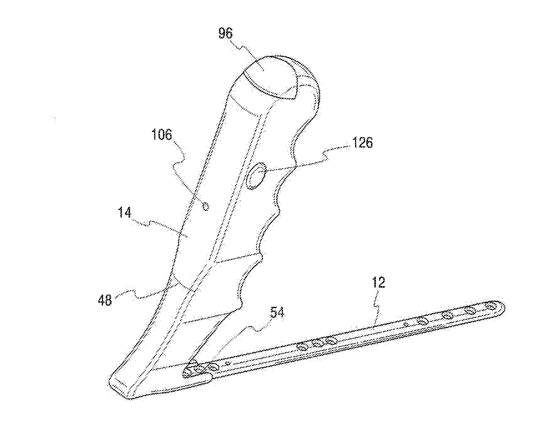
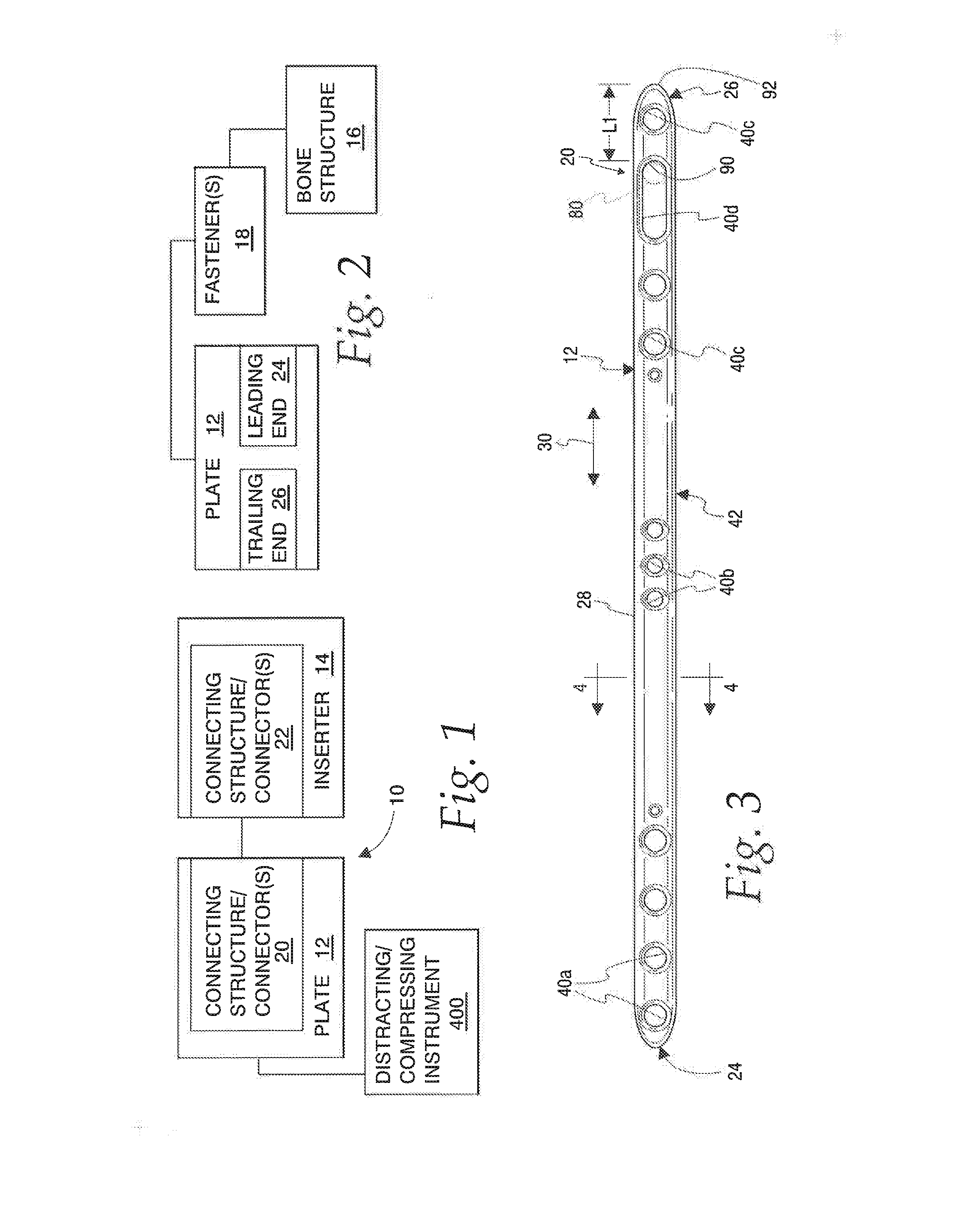
[0059]In its basic form, the invention is directed to a system, shown schematically at 10 in FIG. 1, consisting of the combination of a plate 12 and an inserter 14 for the plate 12.

[0060]The plate 12 is configured to be operatively placed with respect to bone structure 16 at a fracture site, as shown additionally in FIG. 2, also in schematic form. Plate securement is effected through at least one fastener 18. Through this arrangement, bone portions can be stabilized by the secured plate 12 that bridges a fracture.

[0061]Cooperating connecting structure 20, 22 is provided respectively on the plate 12 and inserter 14. Each of the connecting structures 20, 22 may be in the form of one or more connectors. The connecting structure 20, 22 is configured to allow the plate 12 to be releasably maintained operatively engaged with the inserter 14.

[0062]The operatively engaged plate 12 is movable together with the inserter 14, whereby a user can reorient and advance the operatively engaged plate...


PUM


Abstract

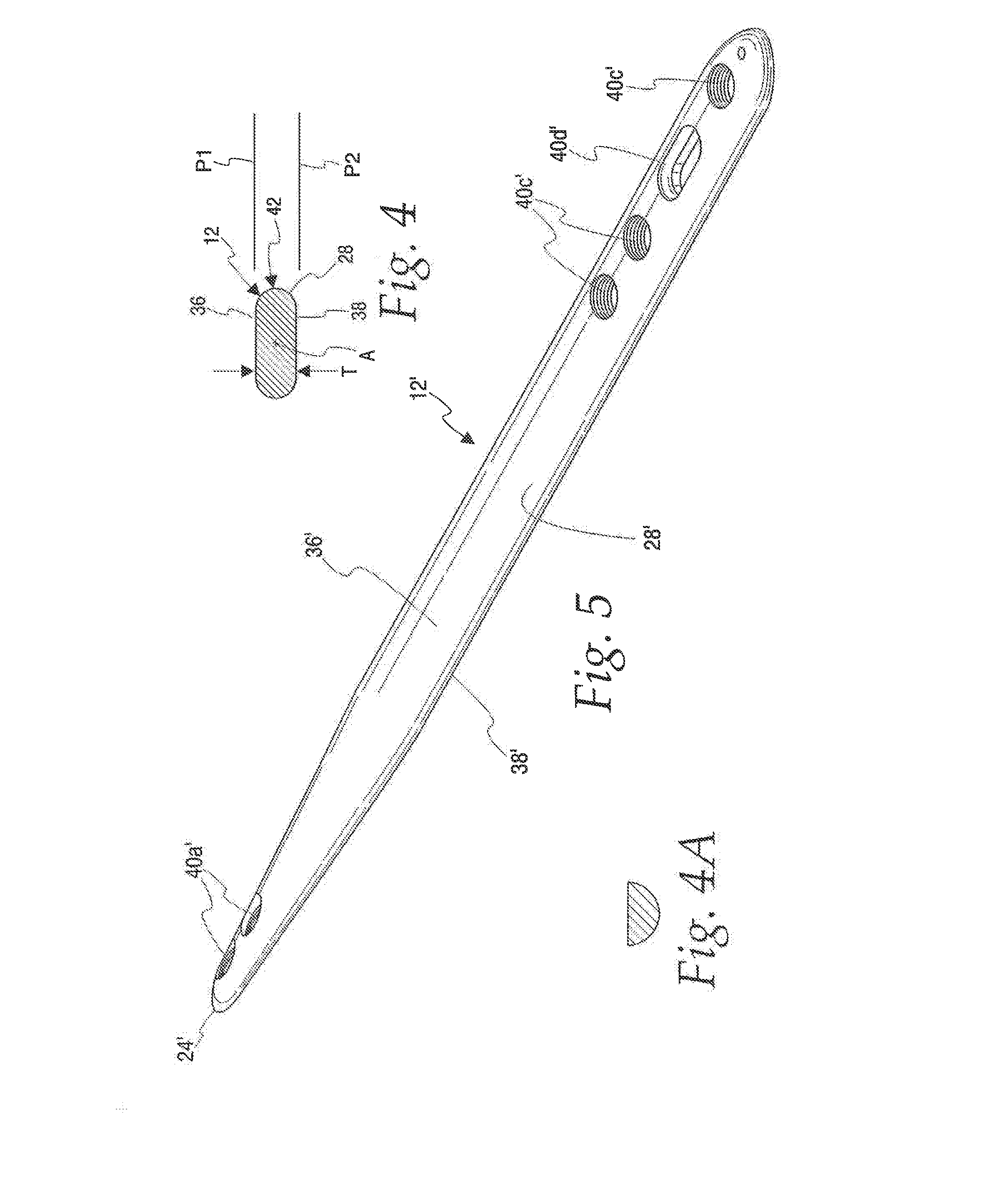
The combination of a plate and inserter for the plate. The plate is configured to be operatively placed at a bone fracture site and secured with at least one fastener to stabilize bone portions between which a fracture is located. Structure cooperating between the plate and inserter is configured to releasably maintain the plate operatively engaged with the inserter. The operatively engaged plate is movable together with the inserter whereby a user can manipulate the operatively engaged plate through the inserter. The plate has a leading end with a tapered configuration to facilitate dissection of soft tissue from a bone surface to allow a surface on the plate that trails the advancing leading end to be operatively placed against the bone surface across the bone fracture site.

Description

CROSS-REFERENCE TO RELATED APPLICATIONS[0001]This is a non-provisional application claiming priority to U.S. Provisional Ser. No. 62 / 187,545, filed Jul. 1, 2015, entitled “Method of Securing a Plate to a Bone at a Fracture Site Utilizing a Detachable Inserter”, which is hereby incorporated by reference in its entirety.BACKGROUND OF THE INVENTION[0002]Field of the Invention[0003]This invention relates to bone fractures and, more particularly, to a plate and inserter combination that can be used to operatively place and secure the plate at a desired location at a fracture.[0004]Background Art[0005]Minimal insertion surgery, or MIS, is a technique in which a plate is inserted along the surface of a bone through a small incision. The surgeon first makes a limited incision and dissects down to the bone surface, and then uses an instrument to dissect through soft tissues for a distance far enough to produce a channel to accept the plate length desired. Once this is done, a plate is applie...

Claims


Application Information

Patent Timeline
IPC IPC(8): A61B17/80A61B17/32
CPCA61B17/808A61B17/8061A61B2017/320044A61B2017/00424A61B2017/0046A61B17/32A61B2017/320056A61B17/80A61B2017/00469
Inventor MEDOFF, ROBERT
Owner TRIMED
Learn More