Minor water leak prevention apparatus for water inlet valve

a technology for water inlet valves and water leak prevention devices, which is applied in the direction of valve actuation floats, valve operating means/releasing devices, transportation and packaging, etc., can solve the problems of water resources being wasted, water tank malfunctions, etc., and achieves effective prevention of water leakage, large suction force, and water resources saving

Active Publication Date: 2017-01-05
LAB XIAMEN SANITARY FITTINGS
View PDF15 Cites 8 Cited by
  • Summary
  • Abstract
  • Description
  • Claims
  • Application Information

AI Technical Summary

Benefits of technology

[0006]An object of the present invention is to provide a minor water leak prevention apparatus for a water inlet valve, which stops water ingress through the water inlet valve when minor water leak occurs in a water tank so as to help save water resources.
[0016]Since the siphon tube is formed with the air aperture, after stop of water supply, the water levels in inside and outside tube of the siphon tube are the same. During normal water discharging, since the water level outside the water container of the water inlet valve drops quickly, water contained in the counterweight water compartment of the counterweight buoyance switch is constrained by the water drain hole (small hole) to flow out slowly whereby inside and outside water levels generated during the process of water discharging spontaneously overcome the buoyance from the lower side and changed to gravity to have the opening of the siphon tube blocked. The water level outside the water inlet valve water tank drops and the siphon tube arranged in outside channel is also lowered to generate a pressure difference with respect to the inside channel thereby inducing a siphon effect to automatically drain water from the water container of the water inlet valve (without unlocking device).

Problems solved by technology

However, after a long period of service, the water tank may get malfunctioning, such as imprecise closure of the discharge valve that leads to slow water leaking (minor water leak).
Under such a condition, water is maintained supplied through the water inlet valve and water continuously leaks from the water tank thereby leading to a waster of water resources.

Method used


Image

  • Minor water leak prevention apparatus for water inlet valve
  • Minor water leak prevention apparatus for water inlet valve
  • Minor water leak prevention apparatus for water inlet valve

Examples


Embodiment Construction

[0032]The following descriptions are exemplary embodiments only, and are not intended to limit the scope, applicability or configuration of the invention in any way. Rather, the following description provides a convenient illustration for implementing exemplary embodiments of the invention. Various changes to the described embodiments may be made in the function and arrangement of the elements described without departing from the scope of the invention as set forth in the appended claims.

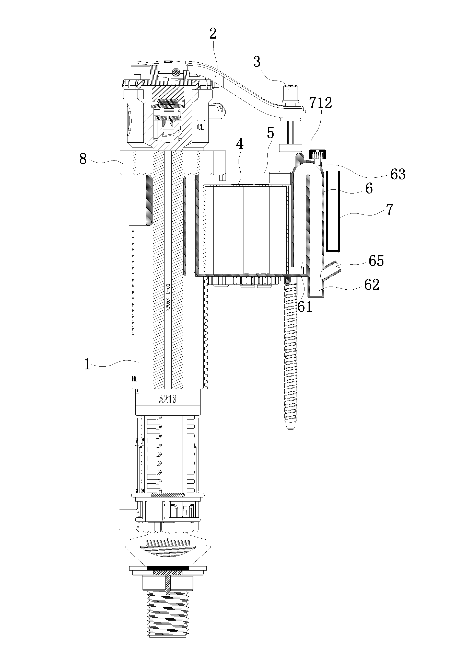
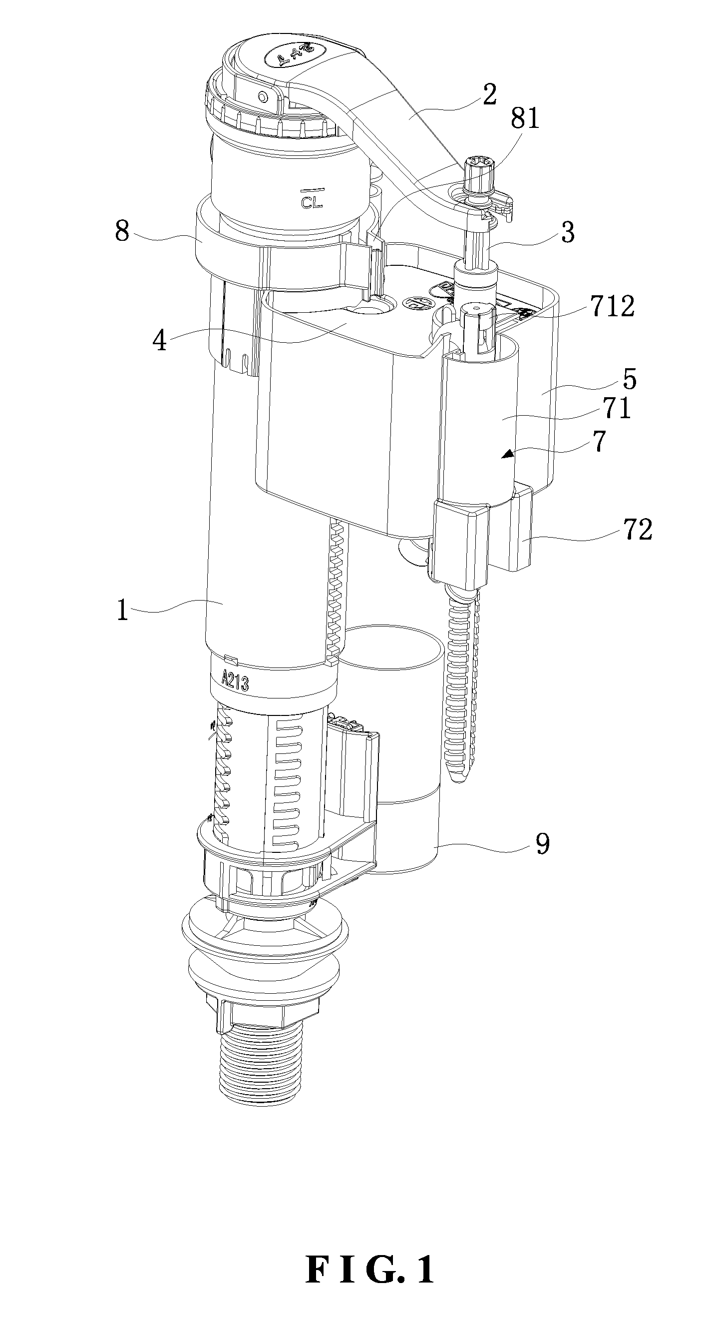
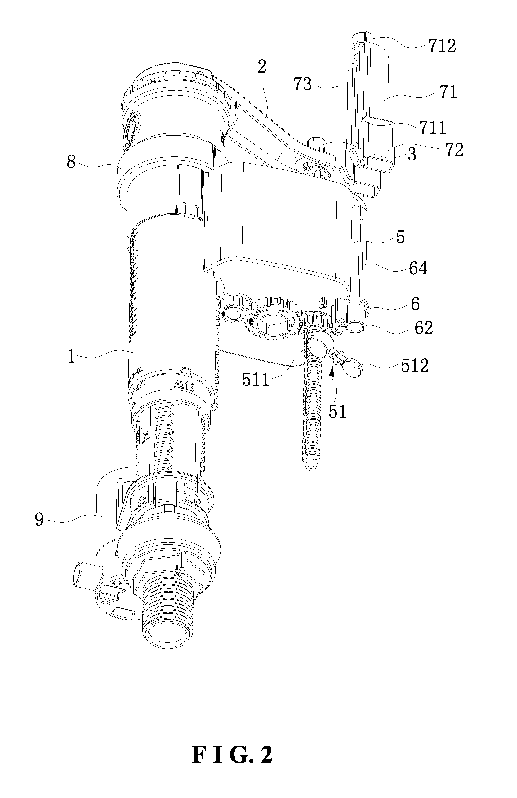
[0033]Referring to FIGS. 1-12, the present invention discloses a minor water leak prevention apparatus for a water inlet valve, which is mounted on a water inlet valve body 1 and comprises a swing arm 2, a regulation bar 3, a float 4, a water container 5, a siphon tube 6, and a counterweight buoyance switch 7.

[0034]As shown in FIG. 10, the swing arm 2 is rotatably mounted to the water inlet valve body 1. The swing arm 2 has an end to which a back pressure pad 21 is mounted to exactly correspond to a...


PUM


Abstract

Disclosed is a minor water leak prevention apparatus for a water inlet valve. A float is mounted on a regulation bar and received in a water container. The water container is mounted on a siphon tube. The siphon tube is formed with an air aperture. A counterweight buoyance switch is mounted on the water container. The counterweight buoyance switch has a counterweight water compartment having a lower end forming a water drain hole. The counterweight water compartment has an upper end to which a closure pressing plate is mounted. The closure pressing plate is opposite to the air aperture. The counterweight buoyance switch controls opening / closing of the air aperture. This arrangement allows water ingress through a water inlet valve to be stopped when minor water leakage occurs in a water tank.

Description

(a) TECHNICAL FIELD OF THE INVENTION[0001]The present invention relates generally to the technical field of water inlet valves, and more particularly to a minor water leak prevention apparatus for water inlet valves.(b) DESCRIPTION OF THE PRIOR ART[0002]Heretofore, a water inlet valve generally comprises a water inlet tube, a top cover, a back pressure pad, a swing arm, a float, and a water container. A lower end of the water inlet tube is mounted to a water supply tube of a water tank. The top cover is set on an upper end on the water inlet tube. The cover is formed with a back pressure hole. The swing arm has a middle section that is pivotally mounted on the top cover. An end of the swing arm corresponds to the back pressure hole and is provided with the back pressure pad. An opposite end of the swing arm is connected to a regulation bar of the float. The float is arranged in the water container and the water container is mounted on the water inlet tube. Sealing members are provid...

Claims


Application Information

Patent Timeline
Patent Type & Authority Applications(United States)
IPC IPC(8): E03D1/33E03D1/32
CPCE03D1/32E03D1/33F16K31/26F16K31/34F16K33/00Y10T137/2849Y10T137/2856Y10T137/7329E03D1/12E03D1/125F16K31/24
Inventor LIU, YONGMAOZHANG, ZIPENG
Owner LAB XIAMEN SANITARY FITTINGS
Why Eureka
Try Eureka