Eureka AIR delivers breakthrough ideas for toughest innovation challenges, trusted by R&D personnel around the world.

Parallel Technique For Computing Problem Functions In Solving Optimal Power Flow

a parallel technique and power flow technology, applied in the field of energy & utility (e & u) industry industry solutions, can solve the problems of high computation complexity of direct consideration of ac power flow constraints, low solution quality, and high computation cost, and achieve low computation cost, high computation cost, and low performan

Active Publication Date: 2017-01-05
UTOPUS INSIGHTS INC
View PDF7 Cites 2 Cited by
  • Summary
  • Abstract
  • Description
  • Claims
  • Application Information

AI Technical Summary

Problems solved by technology

Direct consideration of AC power flow constraints has high computation complexity.
Problems with these approaches include that either the solution quality is low as an approach uses approximated electrical models, or the performance is low with high computation cost.

Method used


Image

  • Parallel Technique For Computing Problem Functions In Solving Optimal Power Flow
  • Parallel Technique For Computing Problem Functions In Solving Optimal Power Flow
  • Parallel Technique For Computing Problem Functions In Solving Optimal Power Flow

Examples


Embodiment Construction

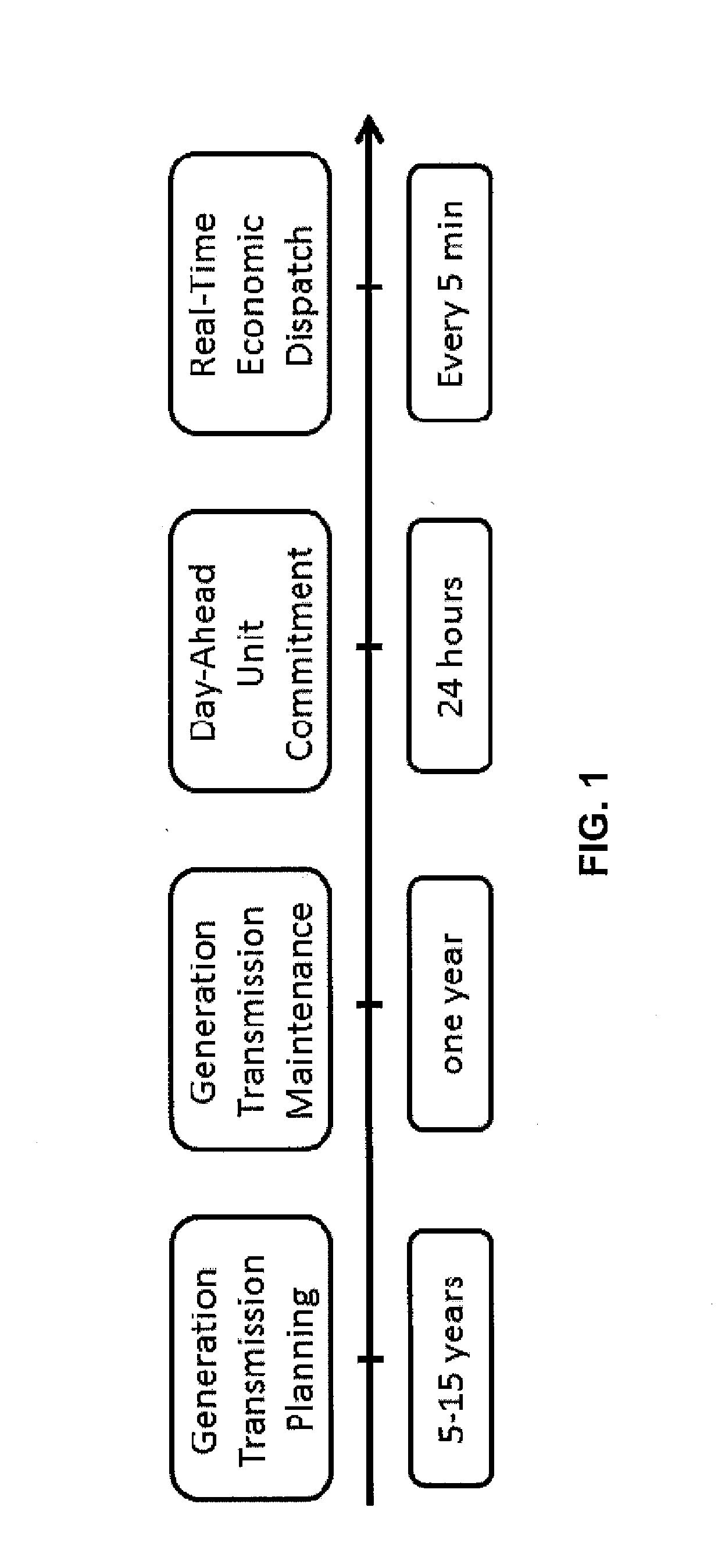
[0017]It is not an exaggeration to say that modern electric power systems are built upon optimization models and solution techniques. FIG. 1 shows a diagram of the major optimization problems in power system operations with a time scale to indicate the horizon of the different types of decisions involved.

[0018]As a simple description, the long-term system planning studies the question of how much new generation and transmission capacity is needed and where in the power system they should be built in order to satisfy a projected future demand in a time horizon of 5 to 15 years or longer; the maintenance scheduling problem aims to optimally schedule the maintenance of generators, transformers, and other equipment so that the system operation will be disturbed as little as possible at a cost as low as possible, where the time horizon of decision is usually one year; the short-term operation problems determine daily or intraday generation schedules to match demand and satisfy various co...


PUM


Abstract

An exemplary method includes solving on a computing system an optimal power flow formulation for a plurality of generators in a power system. The solving includes computing using multi-threaded parallelism a plurality of constraints for the formulation, computing using multi-threaded parallelism a plurality of Jacobian functions of the constraints, and computing using multi-threaded parallelism a Hessian of Lagrangian functions. The method further includes outputting results of the solving, wherein the results comprise values of generation levels for the plurality of generators. Apparatus and program products are also disclosed.

Description

CROSS-REFERENCE TO RELATED APPLICATIONS[0001]This application is a continuation of U.S. patent Ser. No. 14 / 134,351, filed on. Dec. 19, 2013, the disclosure of which is hereby incorporated by reference in its entirety.BACKGROUND[0002]This invention relates generally to industry solutions for the Energy & Utility (E&U) industry and more particularly to E&U operation and planning studies involving optimal power flow.[0003]This section is intended to provide a background or context to the invention disclosed below. The description herein may include concepts that could be pursued, but are not necessarily ones that have been previously conceived, implemented or described. Therefore, unless otherwise explicitly indicated herein, what is described in this section is not prior art to the description in this application and is not admitted to be prior art by inclusion in this section.[0004]Central to an E&U's daily operation and planning studies is to solve an optimal power flow (OPF) proble...

Claims


Application Information

Patent Timeline
Patent Type & Authority Applications(United States)
IPC IPC(8): G05F1/66G06Q50/06
CPCG06Q50/06G05F1/66H02J2203/20H02J3/06H02J3/381G06F7/60G05B2219/35215
Inventor DITLOW, GARYPHAN, DUNGXIONG, JINJUN
Owner UTOPUS INSIGHTS INC
Why Eureka
Eureka Blog
Learn More