Operator seat adjustment system

a seat adjustment and operator technology, applied in the field of seat adjustment system, can solve the problems of operator who is lean, operator may face trouble in maintaining optimal seat position, operator may not be in a comfortable position on the seat,

Inactive Publication Date: 2017-01-12
CATERPILLAR INC
View PDF1 Cites 4 Cited by
  • Summary
  • Abstract
  • Description
  • Claims
  • Application Information

AI Technical Summary

Benefits of technology

[0005]In one aspect of the present disclosure, a seat adjustment system for an operator seat is provided. The seat adjustment system includes a base support and at least two supports which are disposed laterally to the base support. The at least two supports have a plurality of bolsters. The plurality of bolsters are positioned on an inner surface of an operator console. The at least two supports define an operator seating space there between having a fixed maximum capacity. An adjustment module is operatively coupled with the plurality of bolsters. The adjustment module is adapted to selectively inflate the plurality of bolsters for decreasing the operator seating space with respect to the fixed maximum capacity. Further, the adjustment module is adapted to selectively deflate the plurality of bolsters for increasing the operator seating space with respect to the fixed maximum capacity. The adjustment module is adapted to alter a current operator seating capacity with respect to the fixed maximum capacity based on an operator input.

Problems solved by technology

During the operation of the machine on a variety of terrains, such as sand surfaces, mud surfaces, grades, side slopes, or any other uneven surfaces, the operator may face trouble in maintaining an optimal position in the seat.
However, during the operation of the machine, some of the operators may not be in a comfortable position on the seat.
For example, the operator who is lean may have trouble maintaining the optimal position on the seat, if there is too much free space in the seat.
Therefore, the comfort level of the operator may be affected, resulting in decreased productivity.

Method used


Image

  • Operator seat adjustment system
  • Operator seat adjustment system
  • Operator seat adjustment system

Examples


Embodiment Construction

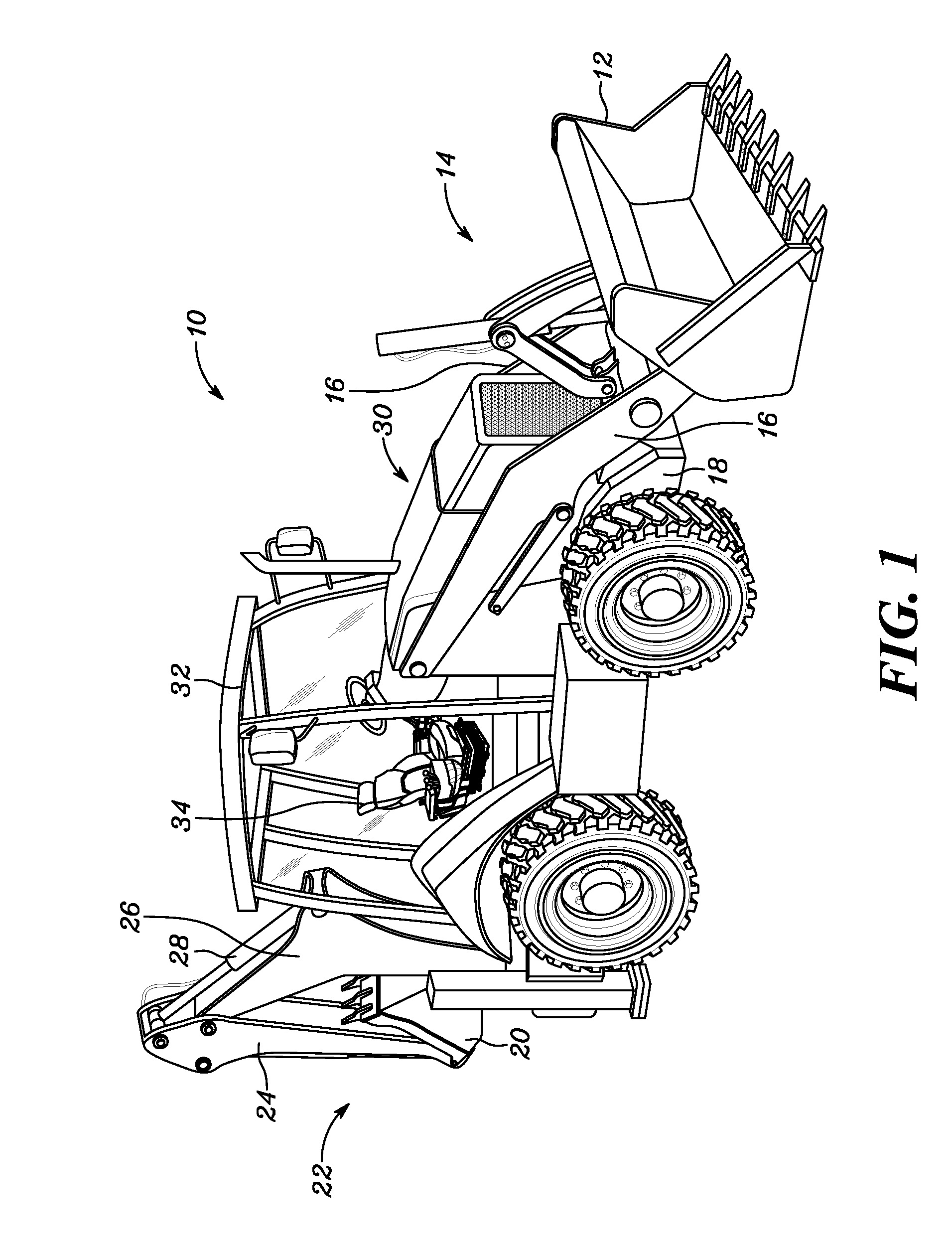
[0012]Referring to FIG. 1, an exemplary machine 10 is illustrated. The machine 10 is used for various operations such as, but not limited to, excavation, or digging operations. The machine 10 includes a loader bucket 12 that is disposed at a first end 14 of the machine 10. The loader bucket 12 is coupled to a pair of loader arms 16. The pair of loader arms 16 is further coupled to a frame 18. Further, the machine 10 includes a backhoe bucket 20 which is disposed at a second end 22 of the machine 10. The backhoe bucket 20 is coupled to an arm 24. The arm 24 is further coupled to a boom 26 via a hydraulic cylinder 28.

[0013]The machine 10 further includes an engine assembly 30 which is disposed at the first end 14 of the machine 10. The engine assembly 30 includes an engine (not shown) that is configured to provide power to the machine 10. Further, the machine 10 includes an operator cabin 32 having multiple controls for operating the machine 10. The operator cabin 32 includes an opera...


PUM


Abstract

A seat adjustment system for an operator seat is provided. The seat adjustment system includes a base support and at least two supports which are disposed laterally to the base support. The at least two supports have a plurality of bolsters. The bolsters are positioned on an inner surface of an operator console. The at least two supports define an operator seating space therebetween having a fixed maximum capacity. An adjustment module is operatively coupled with the bolsters. The adjustment module is adapted to selectively inflate the bolsters for decreasing the operator seating space with respect to the fixed maximum capacity. The adjustment module is adapted to selectively deflate the bolsters for increasing the operator seating space with respect to the fixed maximum capacity. The adjustment module is adapted to alter a current operator seating capacity with respect to the fixed maximum capacity based on an operator input.

Description

TECHNICAL FIELD[0001]The present disclosure relates to a seat adjustment system, and more specifically, to the seat adjustment system for an operator seat.BACKGROUND[0002]Machines, such as hydraulic excavators, bulldozers, or dump trucks, are used for performing various operations. Typically, the machines include an operator cabin which has multiple controls for operating the machine. The operator cabin includes a seat in which an operator sits and operates the machine. During the operation of the machine on a variety of terrains, such as sand surfaces, mud surfaces, grades, side slopes, or any other uneven surfaces, the operator may face trouble in maintaining an optimal position in the seat.[0003]Currently, the seat is designed to accommodate a wide range of operator sizes. However, during the operation of the machine, some of the operators may not be in a comfortable position on the seat. For example, the operator who is lean may have trouble maintaining the optimal position on t...

Claims


Application Information

Patent Timeline
Patent Type & Authority Applications(United States)
IPC IPC(8): B60N2/44B60N2/38B60N2/90
CPCB60N2/4415B60N2/4492B60N2/38B60N2/914B60N2/797B60N2/99
Inventor RANDLEMAN, SEAN A.
Owner CATERPILLAR INC
Why Eureka
Try Eureka