Fiber module rack system

a fiber module and rack technology, applied in the direction of fiber mechanical structures, instruments, optics, etc., can solve the problems of long working hours, significant increase in maintenance and replacement time, and the structural design of the conventional high-density fiber optic cassette is difficult to effectively save working hours and costs, and achieves easy and fast mounting or disassembly. , the effect of saving working hours and costs

Active Publication Date: 2017-01-12
CORNING OPTICAL COMM LLC
View PDF2 Cites 24 Cited by
  • Summary
  • Abstract
  • Description
  • Claims
  • Application Information

AI Technical Summary

Benefits of technology

[0011]A primary objective of the present disclosure is to provide a fiber module rack system in which a rack includes a plurality of frame plates disposed on a base panel thereof and arranged in interval, and each two adjacent frame plates define a receiving space, a plurality of track members are disposed on two opposite sidewalls of the receiving space, the track member has at least one retaining hole formed on an inside wall thereof and adjacent to front opening of the receiving space, so that shell bodies of the fiber optic cassettes can be respectively mounted in the receiving spaces of the rack, the sliding tracks at two opposite sides of the shell body can be respectively mounted into the track members, and a resilient locking member formed between the sliding track and at least one side of the shell body is clasped in the retaining hole for stably being blocked and positioned and preventing withdrawal. The user can laterally press a pulling member of the resilient locking member to simultaneously release the protrusion from the retaining hole, and the shell body of fiber optic cassette can be removed out from the rack. Therefore, the user can easily and quickly mount or dismount the fiber optic cassette without using tool, which results in working hour and cost saving and further achieves effects of stable structure and simple operation and improves production efficiency and convenience in maintenance and replacement.
[0012]A secondary objective of the present disclosure is to provide the base panel of the rack comprising an outer cover disposed at the top thereof, and the outer cover has hollow parts cut therethrough and respectively extended backwardly from the front opening, the shell body of the fiber optic cassette includes an outer shell and a top lid, and top lid has a bent edge formed at a front part thereof and folded backwardly, and step-like bent edge of the top lid can be flushed with the outer cover of the rack after the fiber optic cassette is inserted into the rack completely, so that the space of the rack with limited height can be used efficiently. In normal application, the optical fiber connectors arranged in parallel and plugged with the fiber module have gaps to allow the user's finger to plug or pull the optical fiber connectors without using extra tool. The fiber optic cassettes longitudinally stacked in the receiving spaces of the rack have an installation gap in vertical direction, so that various types of optical fiber connectors can be operated without using any installation tool and not interfered with each other.
[0013]Another objective of the present disclosure is to provide the fiber optic cassette in which the outer shell and the bent edge of the top lid have a plurality of openings adjacent to the installing holes and horizontally arranged in interval, and the fiber module has an optical fiber connector disposed in a docking slot behind a socket thereof and a locking member disposed at the top thereof for being clasped in the docking slot and exposed out of the opening. There is no operating space for the user's finger subject to the limited space of the chamber inside the shell body, so the user can operate a tool (such as tweezers or a screwdriver) to press the locking member of the optical fiber connector through the opening, to dismount the locking member from the docking slot of the socket, so that the optical fiber connector can be removed to complete the operation of disassembly.
[0014]Another objective of the present disclosure is that when the fiber optic cassettes are respectively mounted into the receiving spaces of the rack, the sliding tracks of the shell body are slid into and constrained by the track members of the frame plate, so that the fiber optic cassettes can be smoothly inserted into the receiving spaces of the rack. The sliding track and the track member of the frame plate are respectively made by metal and non-metal materials, so the friction therebetween can be maximally reduced to prevent their surface from scratch or damage during long-term use. With self-lubricating property of the material of the frame plate and good structural strength of the material of the sliding track, the fiber optic cassette can be supported better and inserted into the rack more easily and smoothly.
[0015]Another objective of the present disclosure is that when the user wants to remove the fiber optic cassettes from the rack, the user can just laterally press the pulling member of the resilient locking by single hand, to resiliently deform the pulling member about the bent section to move the pulling member towards the fiber module, and simultaneously release the protrusion from the retaining hole of the front part of the frame plate, and then pull the pulling member outwardly, so that the sliding tracks of the shell body can be moved out along the track members of the two adjacent frame plates. The resilient locking member is made by metal material and has good elasticity to not easily produce metal fatigue, so that the user can have elastic feeling in pressing.
[0016]Another objective of the present disclosure is that the rack is separated by the plurality of frame plates to form the plurality of receiving spaces for receiving the six fiber optic cassettes, and each of the fiber modules of the two fiber optic cassettes longitudinally stacked in one of the receiving spaces includes two sockets arranged in array, and each of the sockets has docking slots disposed at front and rear sides thereof and horizontally arranged in interval for connecting six single-core LC or SC optical fiber connectors, so as to assemble the rack compliant with the standard specification of 1 RU. The rack can totally provide 216 single-core LC or SC optical fiber connectors for further connection. The socket of the fiber module can be replaced by simplex or duplex MPO connector upon actual application, so that more optical fiber connectors can be installed in the fiber optic cassette with the higher density.

Problems solved by technology

However, subject to the standard size of the given specification of 1 RU rack, the manufacturer must research how to install more optical fiber connectors in the limited space and simplify difficulty in configuration of the high-density fiber optic cassettes received inside the rack-type optical fiber containing box, and difficulty in the manners of fastening, dismounting and replacement, so as to satisfy the requirement for optimizing space configuration of the high-density fiber optic cassettes and effectively solving the problem of limited bandwidth due to insufficient transmission channels.
However, the conventional high-density fiber optic cassette is fastened in the rack-type optical fiber containing box by screw-locking manner, so the user must operate a tool to align the screw with the thread hole first for further locking operation, which results in long working hour, inconvenience and significantly-increased time in maintenance and replacement.
That is, the structural design of the conventional high-density fiber optic cassette is hard to effectively save working hour and cost and is lack of practicability.

Method used


Image

  • Fiber module rack system
  • Fiber module rack system
  • Fiber module rack system

Examples


Embodiment Construction

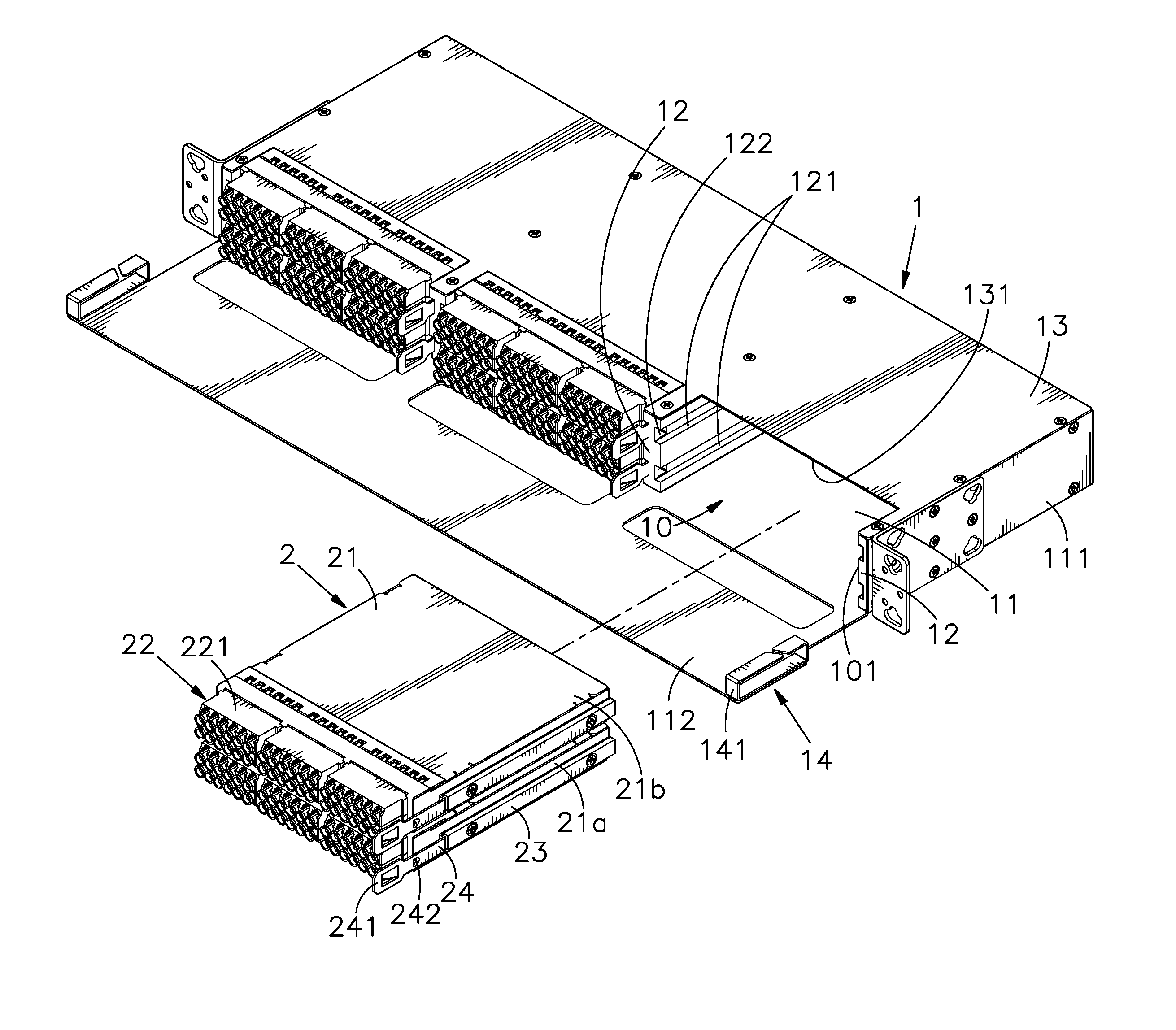
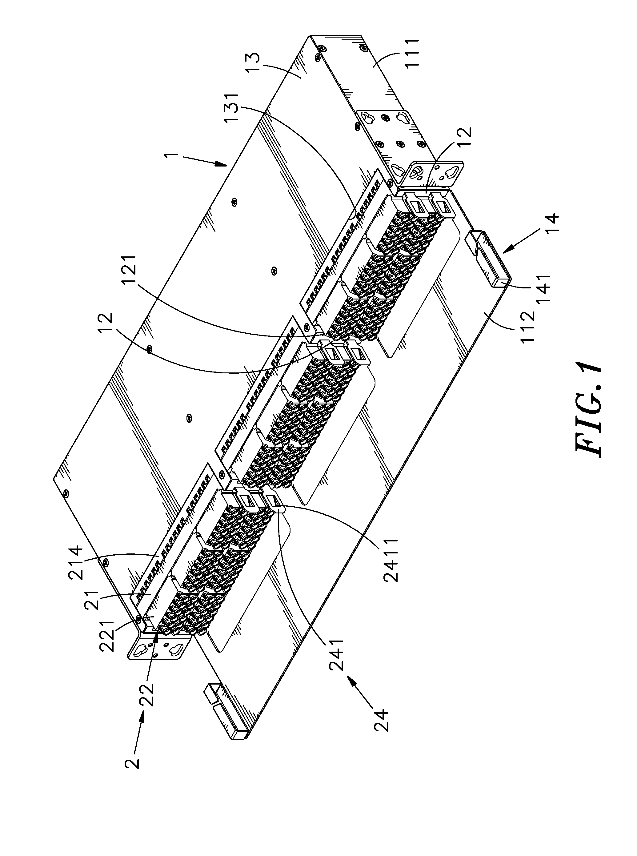
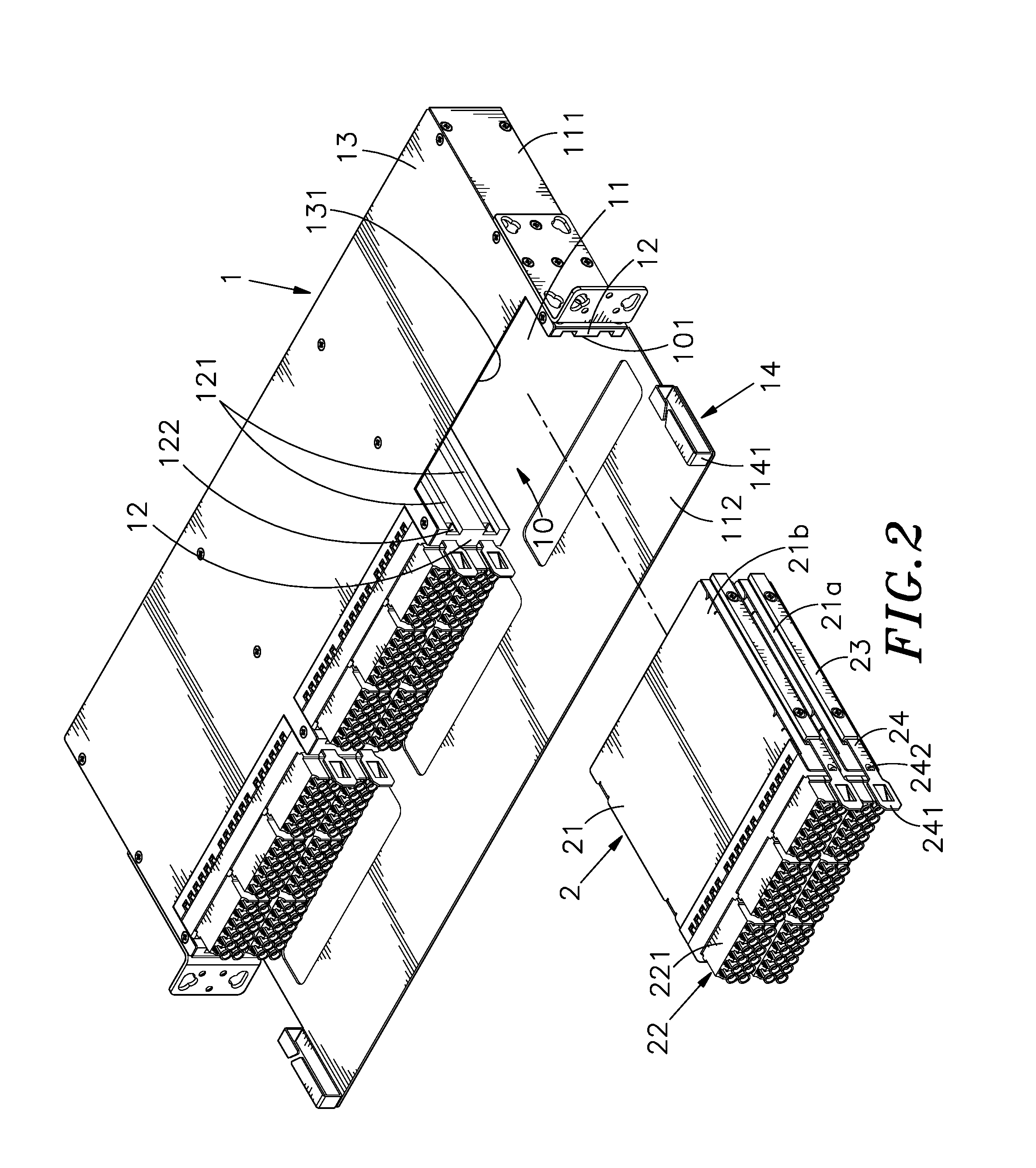
[0030]Reference will now be made in detail to the exemplary embodiments of the present disclosure, examples of which are illustrated in the accompanying drawings. Therefore, it is to be understood that the foregoing is illustrative of exemplary embodiments and is not to be construed as limited to the specific embodiments disclosed, and that modifications to the disclosed exemplary embodiments, as well as other exemplary embodiments, are intended to be included within the scope of the appended claims. These embodiments are provided so that this disclosure will be thorough and complete, and will fully convey the inventive concept to those skilled in the art. The relative proportions and ratios of elements in the drawings may be exaggerated or diminished in size for the sake of clarity and convenience in the drawings, and such arbitrary proportions are only illustrative and not limiting in any way. The same reference numbers are used in the drawings and the description to refer to the ...


PUM


Abstract

The present disclosure illustrates to a fiber module rack system in which a rack includes receiving spaces which each is formed by two frame plates of a base panel. Shell bodies of fiber optic cassettes are mounted in the receiving spaces, and a fiber module is disposed at a front part of the shell body, and a resilient locking member is disposed between the sliding track and at least one side of the shell body, so that the user can quickly and easily dismount the fiber optic cassettes from the rack without using tool.

Description

[0001]This reference is based on Provisional Application Ser. No. 62 / 231,521, filed on Jul. 9,2015, currently pending.BACKGROUND OF THE INVENTION[0002]1. Field of the Invention[0003]The present disclosure relates to a fiber module rack system, more particularly to a rack having receiving spaces which each is formed by two frame plates of a base panel of the rack, wherein shell bodies of fiber optic cassettes are separately mounted in the receiving spaces, and a fiber module is disposed at a front part of the shell body, and a resilient locking member is disposed on the shell body and between the sliding track and at least one side of the shell body, so that the user can quickly and easily dismount the fiber optic cassette from the rack without using tool.[0004]2. Description of the Related Art[0005]In recent year, as communication technology and Internet Network are rapidly developed, data center and telecommunication venders continuously make effort in products with high density, h...

Claims


Application Information

Patent Timeline
Patent Type & Authority Applications(United States)
IPC IPC(8): G02B6/44G02B6/38
CPCG02B6/4452G02B6/4453G02B6/3897
Inventor XU, GANGHSU, KUO-FULIU, SHUANG-QIANGLI, YAO
Owner CORNING OPTICAL COMM LLC
Why Eureka
Try Eureka