
Body Heat Powered Wireless Transmitter

a wireless transmitter and body heat technology, applied in the direction of generator/motor, transmission, dc source parallel operation, etc., can solve the problems of not being able to fully utilize not being able to be easily available, and not being able to achieve the effect of utilizing ambient energy through energy harvesting systems

Active Publication Date: 2017-01-12
JOGIA PARESH
View PDF4 Cites 13 Cited by
  • Summary
  • Abstract
  • Description
  • Claims
  • Application Information

AI Technical Summary

Benefits of technology

The present invention is a new product that solves problems with existing RFID tags and personal location trackers. It uses recyclable components and is easy to obtain. The invention also improves an existing energy harvesting system and provides a new one. This system can power or charge batteries of portable products using body heat. Overall, the invention enhances the portability and efficiency of electronic devices.

Problems solved by technology

Attempts to utilize ambient energy by way of energy harvesting systems have not been completely successful.
The reasons include the fact that the energy is not available all of the time, such as solar or kinetic.
Also by the limitation of the minimum ‘Turn On’ voltage of Silicon transistors which are required for the mass production for use within these devices or the many thousands of transistors within the microprocessor integrated circuit which is limited to 0.7 Volts.
However, they are not so readily available and do not lend themselves easily to mass produced integrated circuits (IC) unlike Silicon which is widely used in today's world.
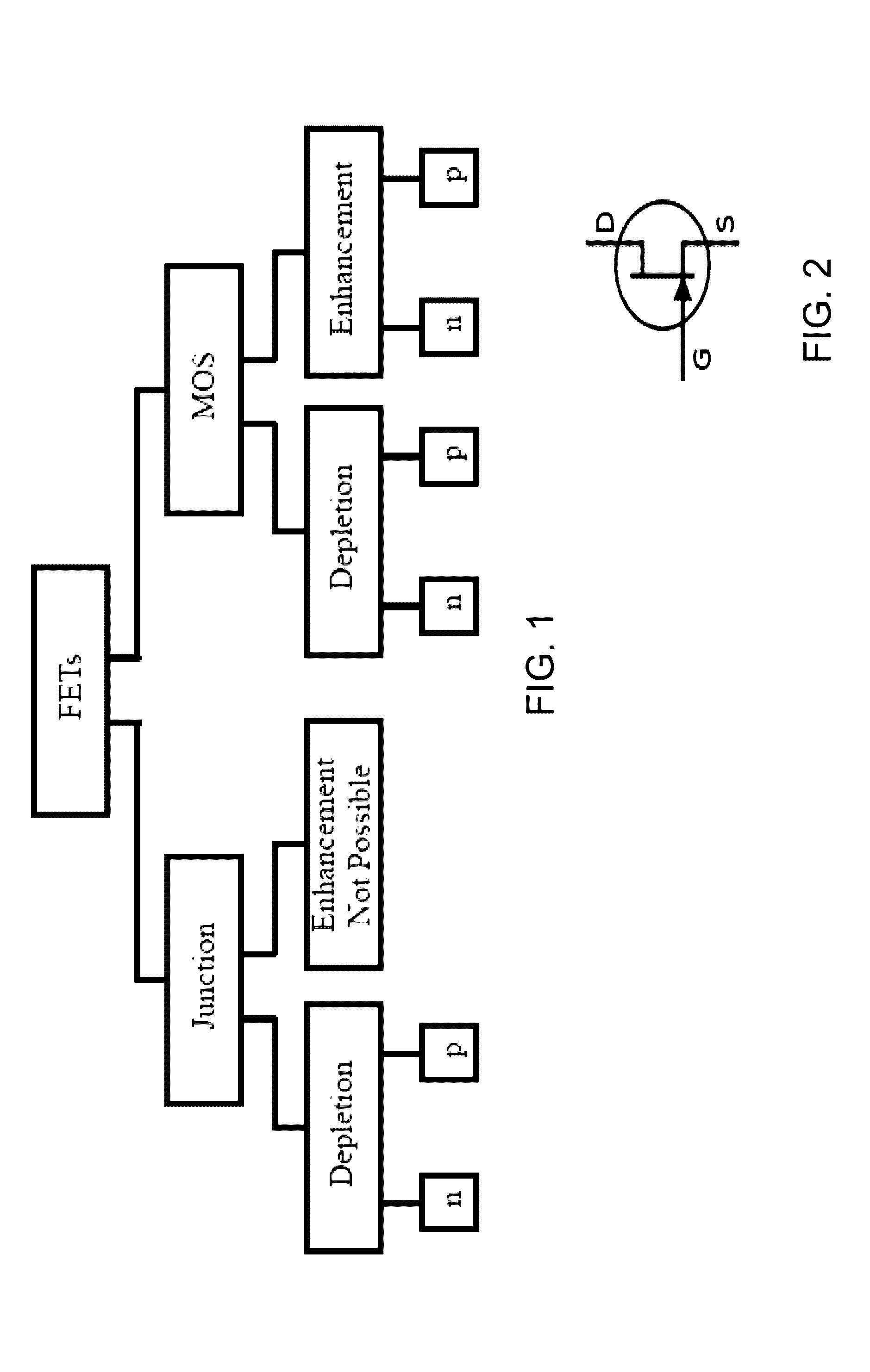
Due to the low IDSS (Drain Source Current) and the relatively high RDS (On), (Drain Source Resistance) of the Depletion Mode FET although outputs of several volts can be achieved, the output power is limited due to the limited current.
However, the resistance across the Gate and Source is relatively high and some current flows.
Due to the low IDSS and the relatively high RDS (On) although outputs of several volts can be achieved, the output power is limited due to the limited current.
The application of the device is limited to remote wireless sensor systems as the charged capacitor is then used as a power source to capture data from sensors, process through a microprocessor and send the data.
For a Depletion Mode FET, the output power is limited.
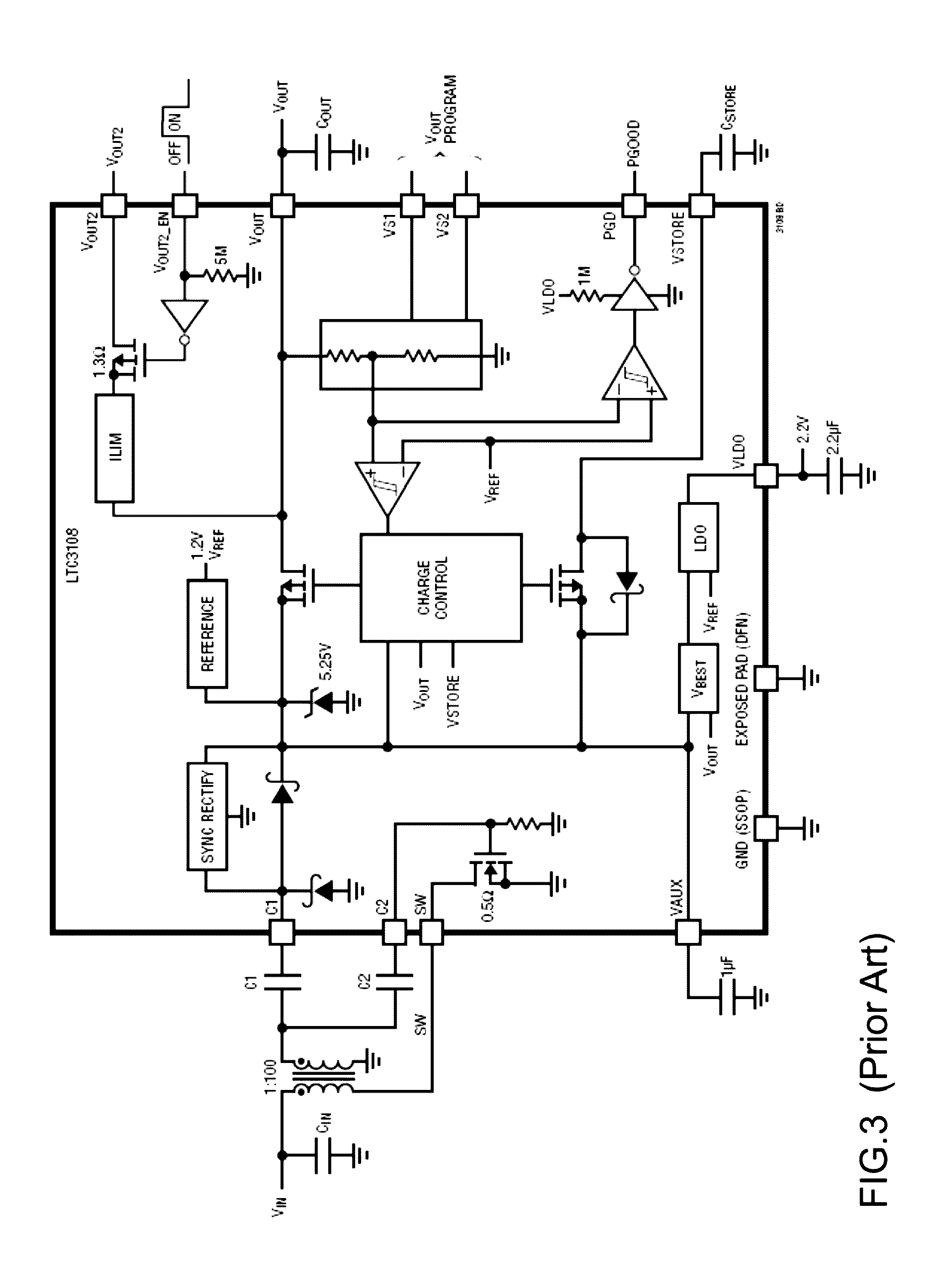
However, the IC is expensive, requires a specific type of step up transformer and requires that the system developer use their device which in turn provides a limited output power that is not instantaneous.
However, the energy harvesting circuit power output would again be limited due to the low IDSS and relatively high RDS(On).
Hence the power is limited for small bursts of data of only 5 microwatts every two minutes and not instantaneous data output which would require significantly greater power output.
However, presently, they are depletion mode MOSFETS.
The output is instantaneous, however there are similar limitations for both patent US 2002074898 (A1)) and the paper entitled ‘A Compact, Wireless, Self-Powered Pushbutton Controller’.
Firstly it requires the pressing of a piezo electric switch to generate the electrical power which will wear over time.
Secondly, the output power is limited in that it can only charge a 4.4 μF (micro Farad) Capacitor to power an encoder and a RF transmitter to 3 Volts, and transmit a 12-bit digital code sequence for a limited 30 ms (Milliseconds).
For the ID tag application it is aimed for, it has limitations due to the limited 12-bit digital code sequence (due to the frequency limitations and the 30 ms transmit time available) which means only 4096 codes can be obtained.

Method used


Image

  • Body Heat Powered Wireless Transmitter
  • Body Heat Powered Wireless Transmitter
  • Body Heat Powered Wireless Transmitter

Examples


Embodiment Construction

[0092]Certain exemplary embodiments of the present invention are described herein and are illustrated in the accompanying figures. The embodiments described are only for purposes of illustrating the present invention and should not be interpreted as limiting the scope of the invention. Other embodiments of the invention, and certain modifications, combinations and improvements of the described embodiments, will occur to those skilled in the art and all such alternate embodiments, combinations, modifications, improvements are within the scope of the present invention.

Summary of the Problems

[0093]There are several issues that have obstructed development of practical portable electronic systems able to be reliably powered from body heat. These include 1) The system device needs to fit into the form factor of existing battery powered units. The best choice at present is to use a Peltier unit of between 20 mm square and 40 mm square. However, the available voltage is 100 mV maximum for t...


PUM


Abstract

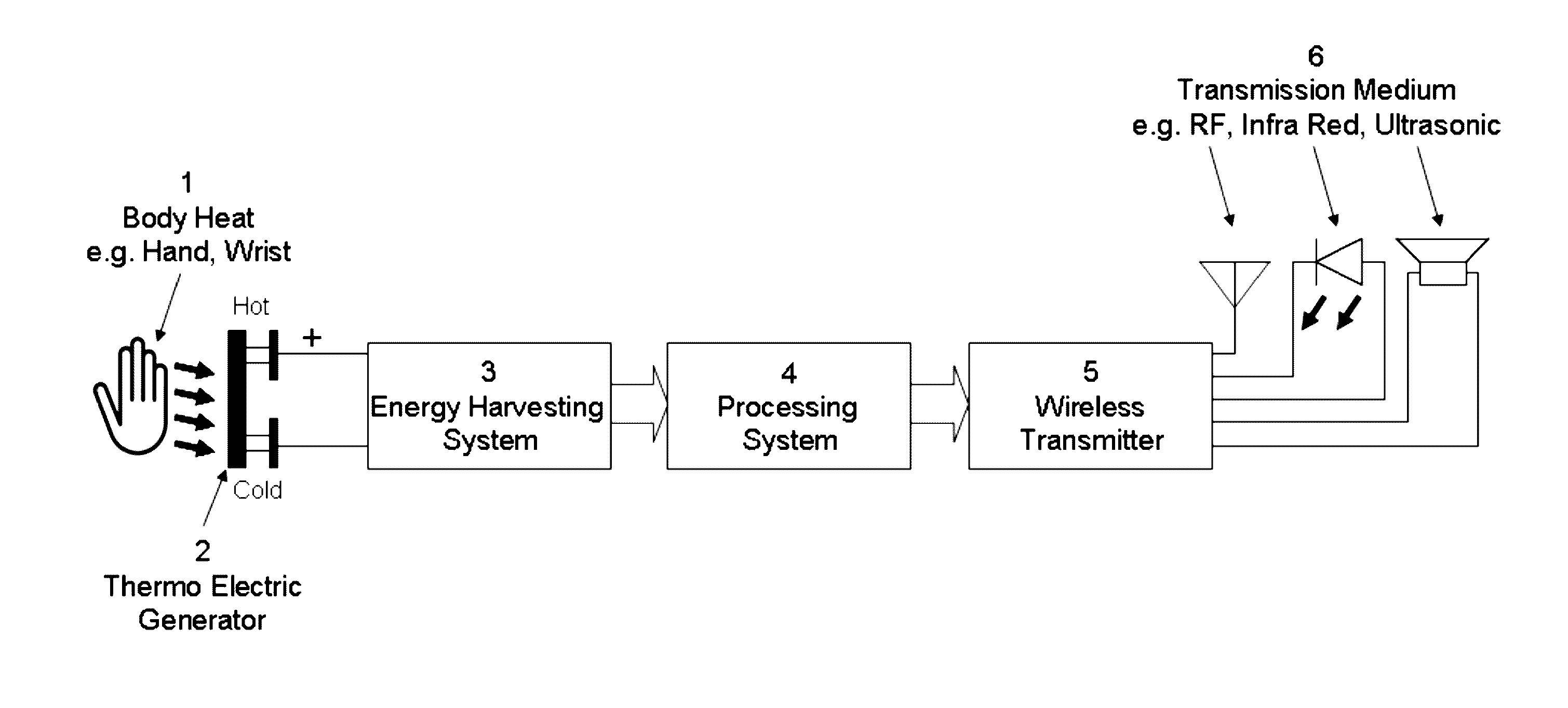
A Body Heat Powered Portable Wireless Transmitter contains a Thermo Electric Generator, an energy Harvesting System, a Control System and a Wireless Transmitter. The Wireless transmission medium could include but not exhaustively, RF, Ultrasonic or Infrared. The application can range from a keyfob transmitter or a Remote Keyless Entry (RKE) System for a car, an infrared remote control for a TV or Hi-Fi or a person location device which can be worn around the wrist like a watch to allow hospital staff to track Alzheimer's patients, allow parents to track their children, detect trapped people from the effects of earthquakes and Tsunamis or an RF ID tag for security purposes. The device can also be used for sensor applications (Wireless Data Capture) such as a fitness tracker or health monitor such as a wireless ECG (Electrocardiogram) monitor to collect patient vitals and wirelessly transmit the data to hospital staff.

Description

CROSS REFERENCE TO RELATED APPLICATIONS[0001]This application claims the benefit of and priority to Great Britain patent application no. GB1412249.3, filed on Jul. 9, 2015; the entirety of which is incorporated by reference herein.FIELD OF THE INVENTION[0002]The present invention concerns, inter alia, improvements in and relating to the power supplies of wireless transmitters and improvements in and relating to portable energy harvesting systems for electrical appliances.BACKGROUND[0003]All modern portable electronic devices will drain their batteries at some point and either require replacing or re-charging. Attempts to utilize ambient energy by way of energy harvesting systems have not been completely successful. The reasons include the fact that the energy is not available all of the time, such as solar or kinetic. Also by the limitation of the minimum ‘Turn On’ voltage of Silicon transistors which are required for the mass production for use within these devices or the many thou...

Claims


Application Information

Patent Timeline
Patent Type & Authority Applications(United States)
IPC IPC(8): H01L35/30H04B1/3827H02N11/00H10N10/00H10N10/13
CPCH01L35/30H04B1/385H02N11/00H02J50/05H02J50/001H02J50/00H02M1/0006H10N10/13H02J7/345H02J1/10H02J7/34H02M3/335H10N10/00
Inventor JOGIA, PARESH
Owner JOGIA PARESH
Learn More