Vitreous cutter with integrated illumination system

a technology of illumination system and laser cutter, which is applied in the field of medical procedures, can solve the problems of reducing illumination efficiency, reducing strength or rigidity, and other visualization, and achieves the effect of minimizing the glare produced

Active Publication Date: 2017-01-19
ALCON INC
View PDF8 Cites 13 Cited by
  • Summary
  • Abstract
  • Description
  • Claims
  • Application Information

AI Technical Summary

Benefits of technology

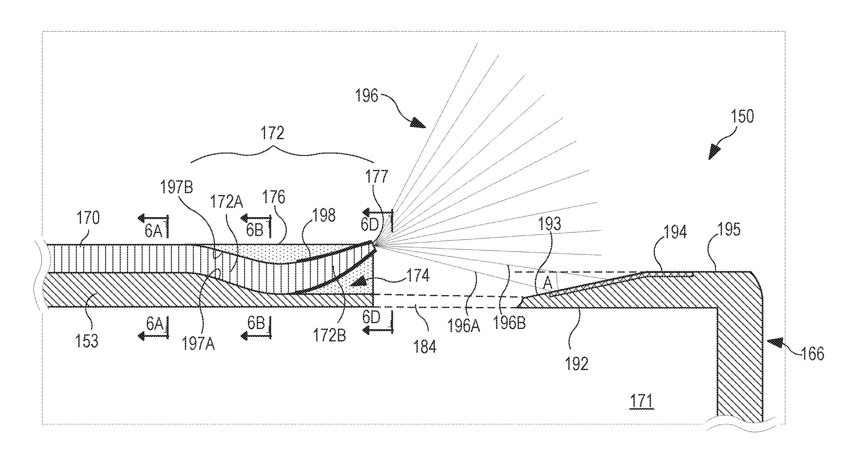
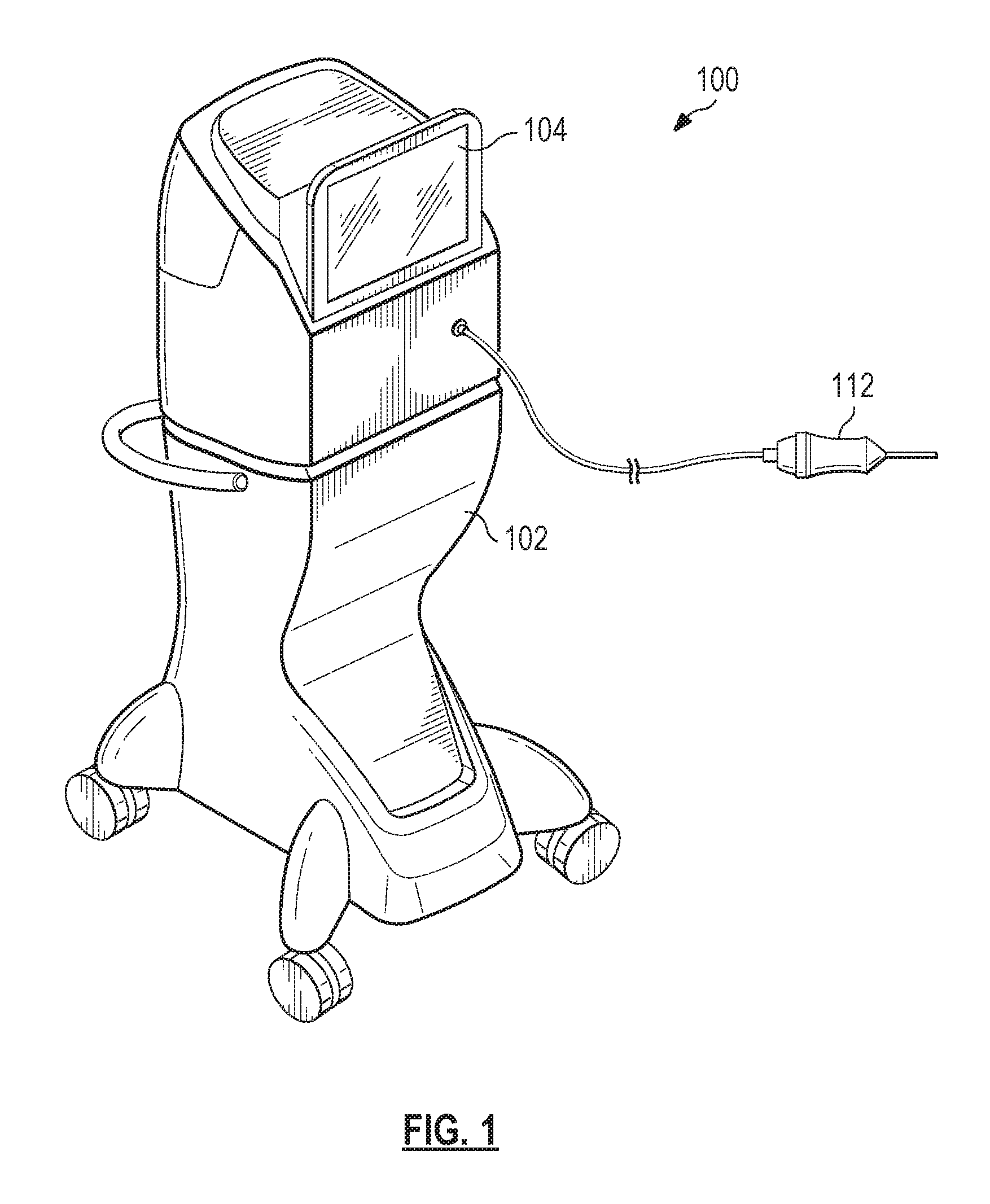
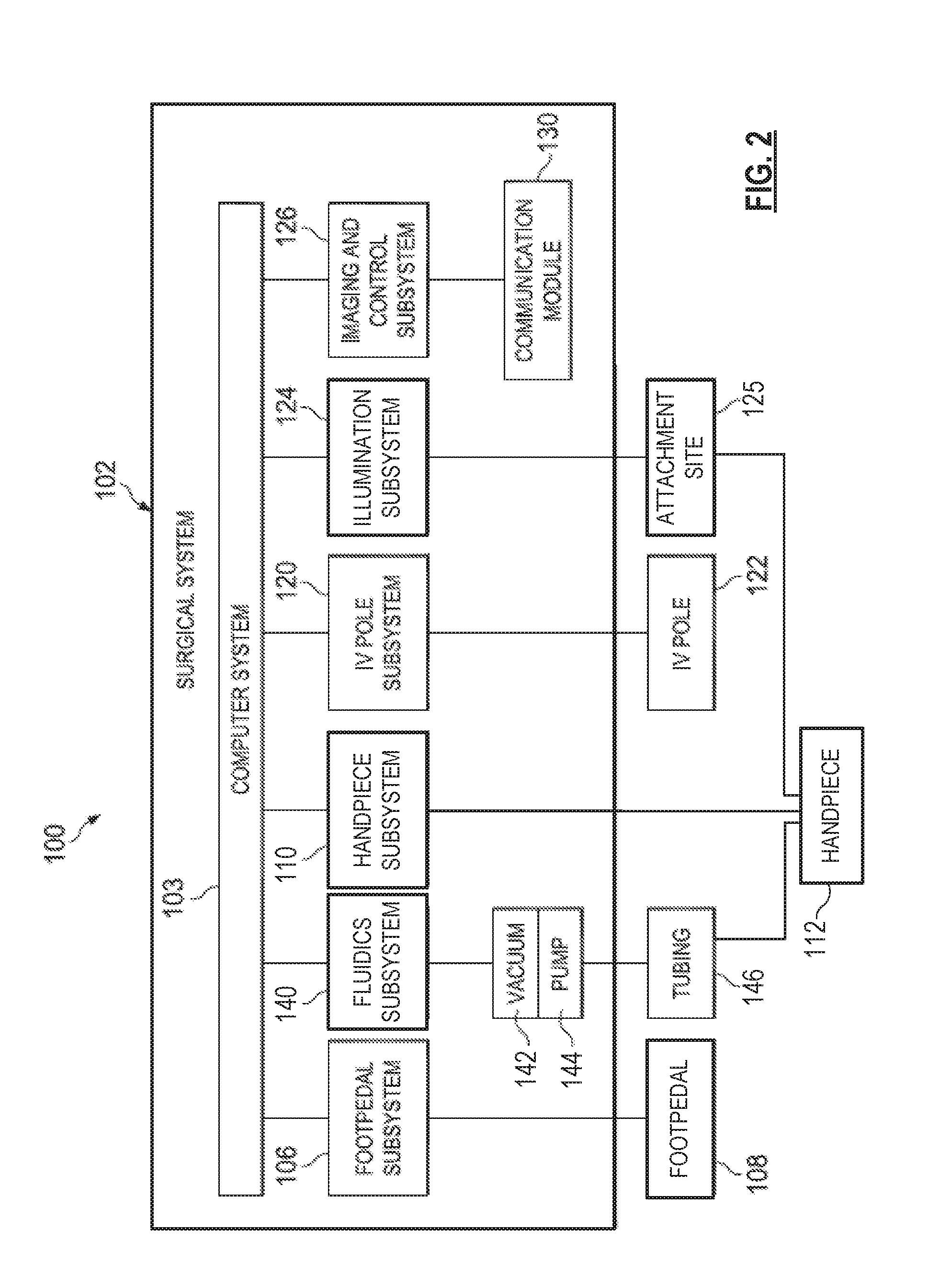
[0007]Exemplary surgical systems are provided herein. An exemplary surgical system may include a light source coupleable to an optical fiber to provide illumination at a distal end of the optical fiber and may further include a vitrectomy subsystem having a vitrectomy cutter. The vitrectomy cutter may include a tubular member with a distal tip and a lumen extending therein. The lumen may be defined by an inner surface of a wall of the tubular member. The distal tip may include a port extending through the wall of the tubular member. The optical fiber may be arranged to deliver light to a surgical site. As such, the optical fiber may include a proximal end for receiving a light beam from the light source and a distal end arranged to emit light adjacent to the port. A portion of the distal end may be positioned within a notch that extends from an outer surface of the tubular member into the wall. A tip of the distal end may be directed away from the tubular member in order to minimize glare produced by the light reflecting off a portion of the tubular member.

Problems solved by technology

However, a reduction in size can result in a reduction in strength or rigidity.
Unfortunately, at least some prior attempts at integrating illuminating optical fibers with microsurgical instruments have resulted in a decrease in illuminating efficiency or in other visualization problems that otherwise adversely effected the distribution of light emitted from the optical fibers.

Method used


Image

  • Vitreous cutter with integrated illumination system
  • Vitreous cutter with integrated illumination system
  • Vitreous cutter with integrated illumination system

Examples


Embodiment Construction

[0019]For the purposes of promoting an understanding of the principles of the present disclosure, reference will now be made to the embodiments illustrated in the drawings, and specific language will be used to describe the same. It will nevertheless be understood that no limitation of the scope of the disclosure is intended. Any alterations and further modifications to the described devices, instruments, methods, and any further application of the principles of the present disclosure are fully contemplated as would normally occur to one skilled in the art to which the disclosure relates. In particular, it is fully contemplated that the features, components, and / or steps described with respect to one embodiment may be combined with the features, components, and / or steps described with respect to other embodiments of the present disclosure. For simplicity, in some instances the same reference numbers are used throughout the drawings to refer to the same or like parts.

[0020]The presen...


PUM


Abstract

An illuminated microsurgical instrument is provided herein that includes a microsurgical instrument having a tubular member arranged to treat patient tissue at a surgical site, the tubular member having a distal tip, an inner surface, and an outer surface. The inner surface defines a lumen. The outer surface has a notch formed therein. The illuminated microsurgical instrument further includes an optical fiber arranged to deliver light to the surgical site. The optical fiber includes a proximal end arranged to receive a light beam from a light source and also includes a curved distal end arranged to emit light adjacent to the distal tip. A portion of the curved distal end is positioned within the notch and curves away from the tubular member.

Description

TECHNICAL FIELD[0001]The present disclosure is directed to methods and systems for medical procedures, and more particularly, to methods and systems involving a need for illumination within a body cavity.BACKGROUND[0002]Vitreo-retinal procedures are commonly performed to treat many serious conditions of the posterior segment of the eye. For example, vitreo-retinal procedures may treat conditions such as age-related macular degeneration (AMD), diabetic retinopathy and diabetic vitreous hemorrhage, macular hole, retinal detachment, epiretinal membrane, cytomegalovirus (CMV) retinitis, and many other ophthalmic conditions.[0003]A surgeon performs vitreo-retinal procedures with a microscope and special lenses designed to provide a clear image of the posterior segment. Several tiny incisions just a millimeter or so in diameter are made on the sclera at the pars plana. The surgeon inserts microsurgical instruments through the incisions, such as a fiber optic light source to illuminate ins...

Claims


Application Information

Patent Timeline
Patent Type & Authority Applications(United States)
IPC IPC(8): A61F9/007A61B90/30
CPCA61F9/00736A61B90/30A61B2017/00973A61B2217/005A61B2217/007A61B2090/306
Inventor KERN, THOMASMIRSEPASSI, ALIREZAPAPAC, MICHAEL J.SMITH, RONALD T.WHEATLEY, BARRY L.
Owner ALCON INC
Why Eureka
Try Eureka