

One axis shutter with a pin-based bus system for miniature circuit breaker load centers
a circuit breaker and load center technology, applied in the direction of coupling device details, protective switch terminals/connections, coupling device connections, etc., can solve the problem of shutting off power to the panelboard as a major inconvenience, and achieve the effect of safe inserting and removing and minimizing the potential for exposur
- Summary
- Abstract
- Description
- Claims
- Application Information
AI Technical Summary
Benefits of technology
Problems solved by technology
Method used
Image

Examples
Embodiment Construction
[0004]The embodiments disclosed herein are directed to methods and systems for reducing or eliminating the possibility of exposure to live parts in a panelboard, and particularly in the load center variety of panelboard, and safely installing and removing a circuit breaker or other branch electrical devices from the energized panelboard. While the illustrated embodiments are explained with load centers in mind, and the terms “load center” and “panelboard” may sometimes be used interchangeably herein, the present invention is not necessarily limited to the miniature circuit breaker load center environment.
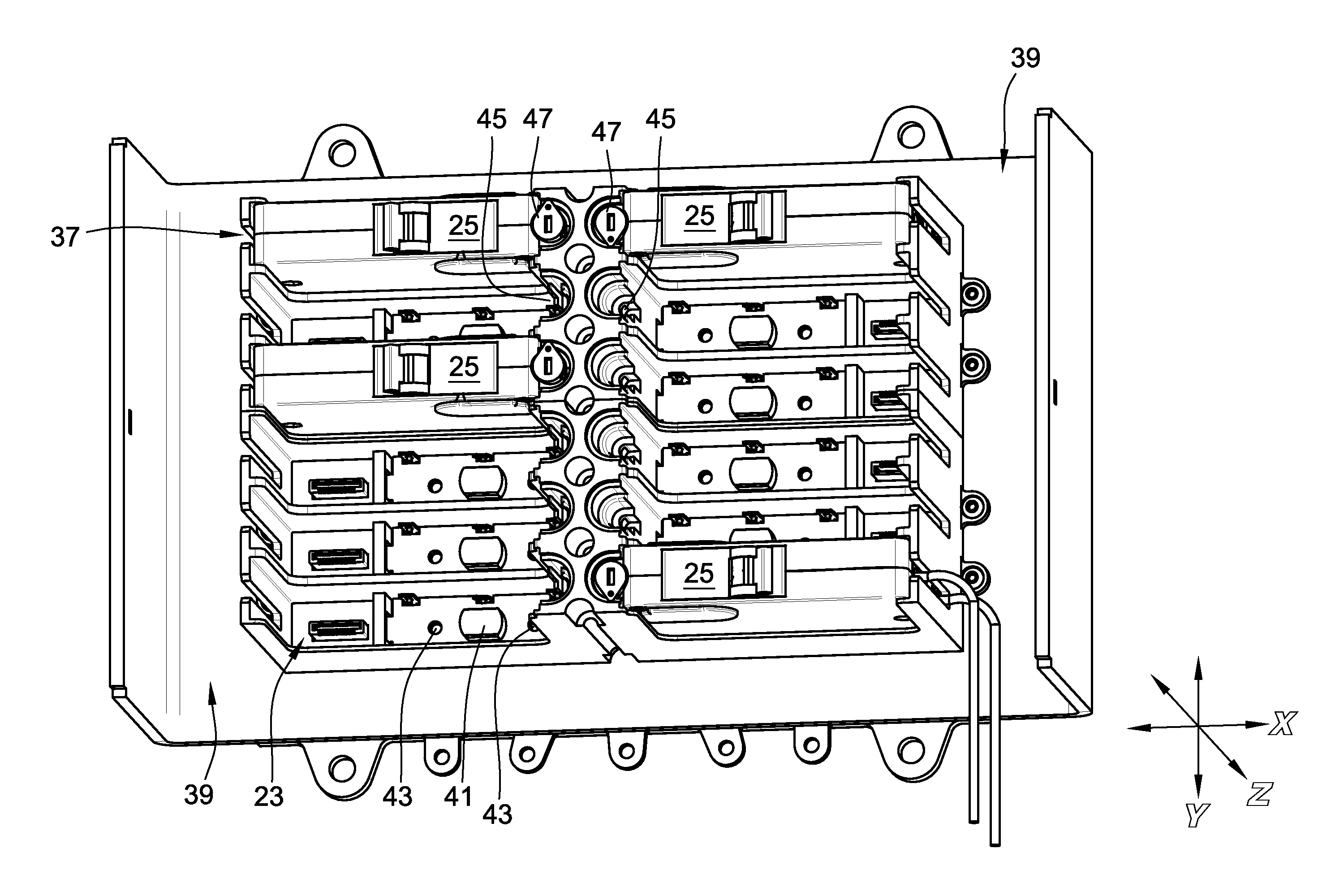
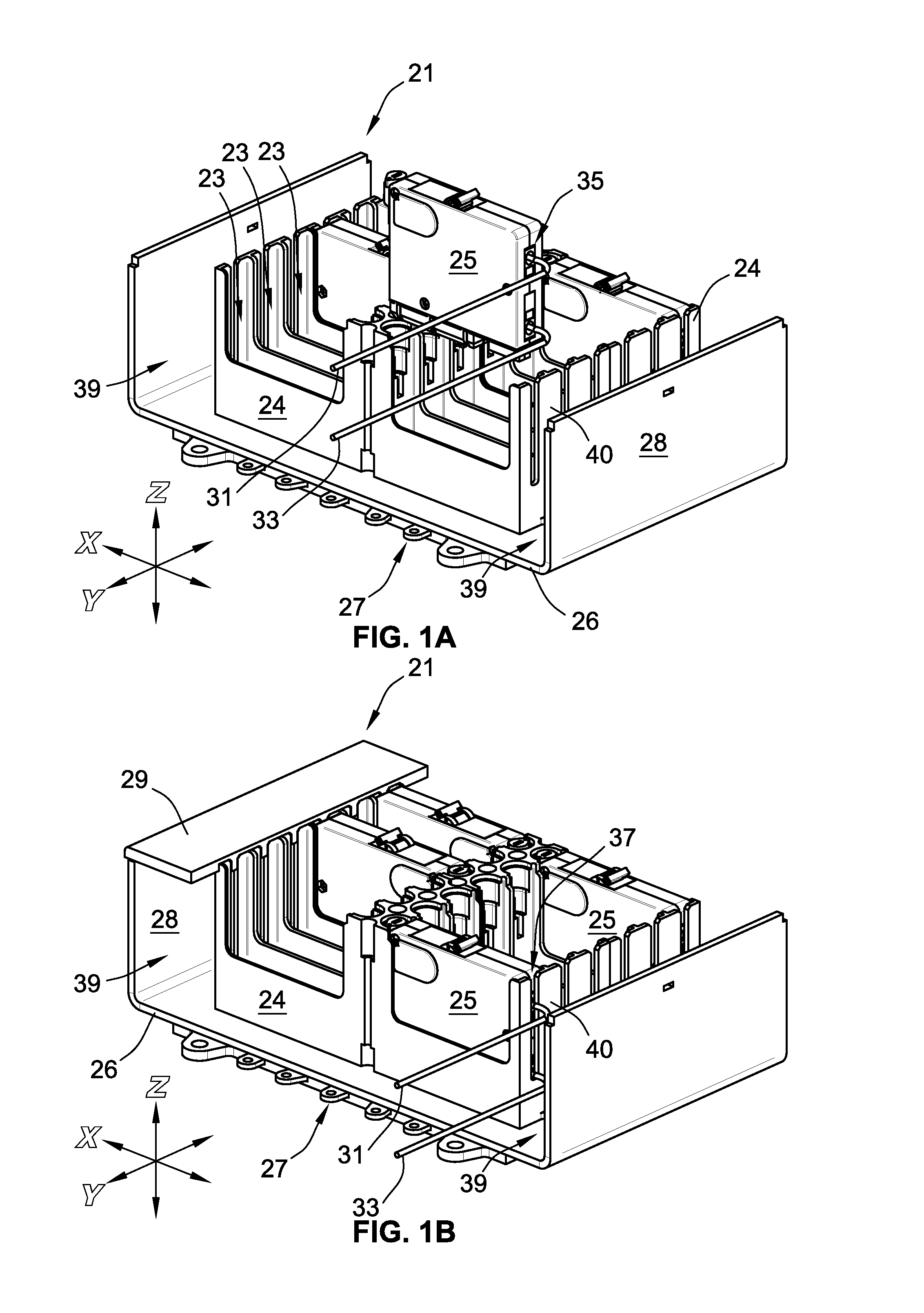
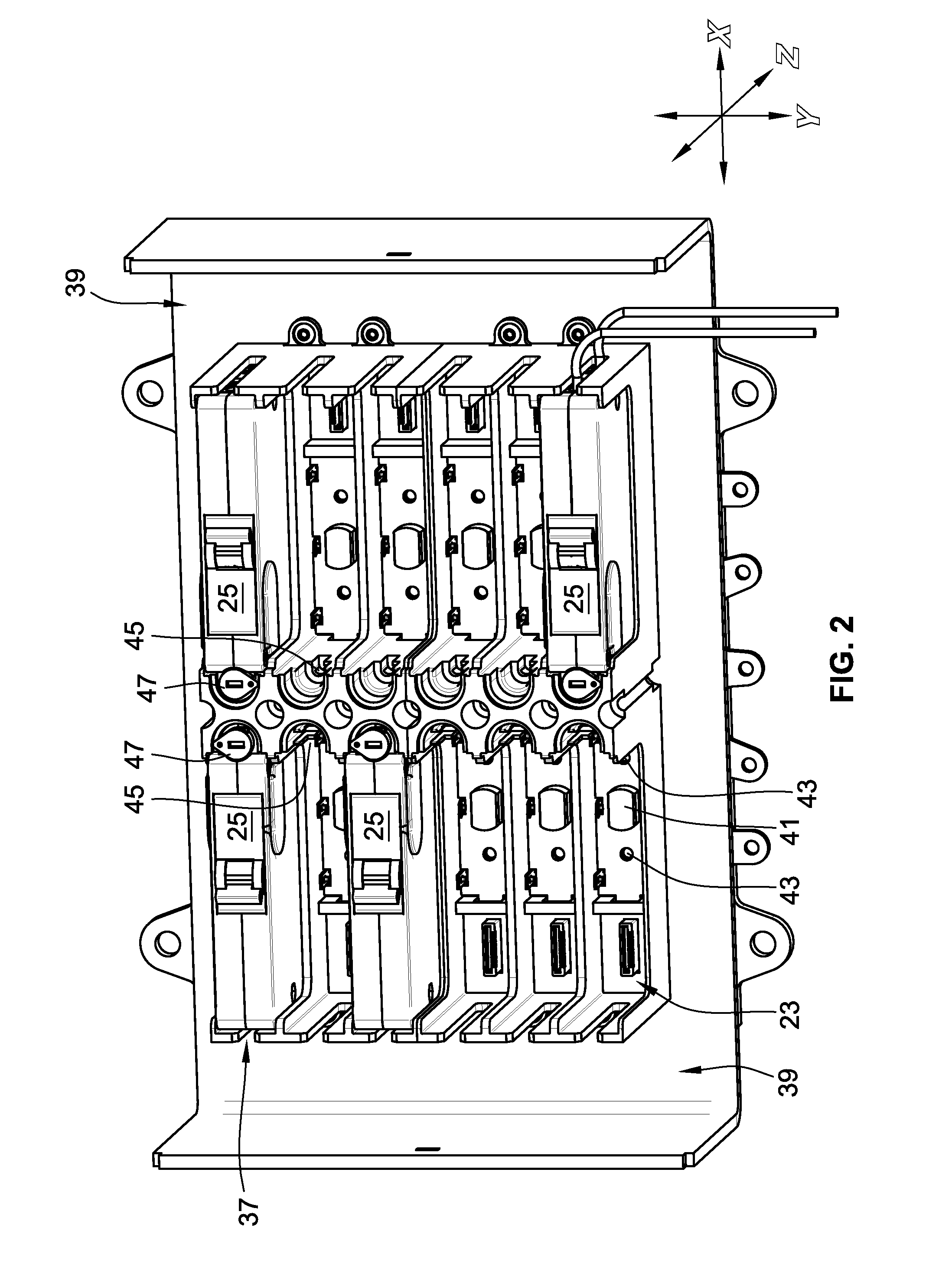
[0005]The disclosed embodiments provide a shutter assembly for the panelboard that automatically closes off access to the conductors in the panelboard until a circuit breaker is inserted in the panelboard. A shutter assembly is attached in the circuit breaker mounting compartments, sometimes referred to herein as “wells,” of the panelboard and serves as one part of a protective barr...
PUM
 Abstract
Description
Claims
Application Information