
Systems and methods for optimizing power and control of a multicolored lighting system

a multi-colored lighting and optimization method technology, applied in the direction of lighting and heating apparatus, semiconductor devices of light sources, light source combinations, etc., can solve the problems of inefficiency, inefficiency of modern led connected lighting technology, and inability to easily reverse the direction of current flow,

Active Publication Date: 2017-01-19
LIGHTING SCI GROUP
View PDF6 Cites 50 Cited by
  • Summary
  • Abstract
  • Description
  • Claims
  • Application Information

AI Technical Summary

Benefits of technology

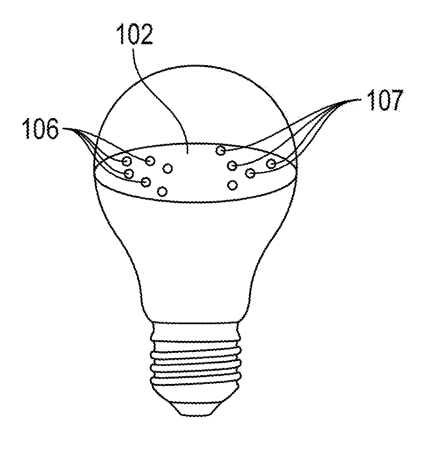
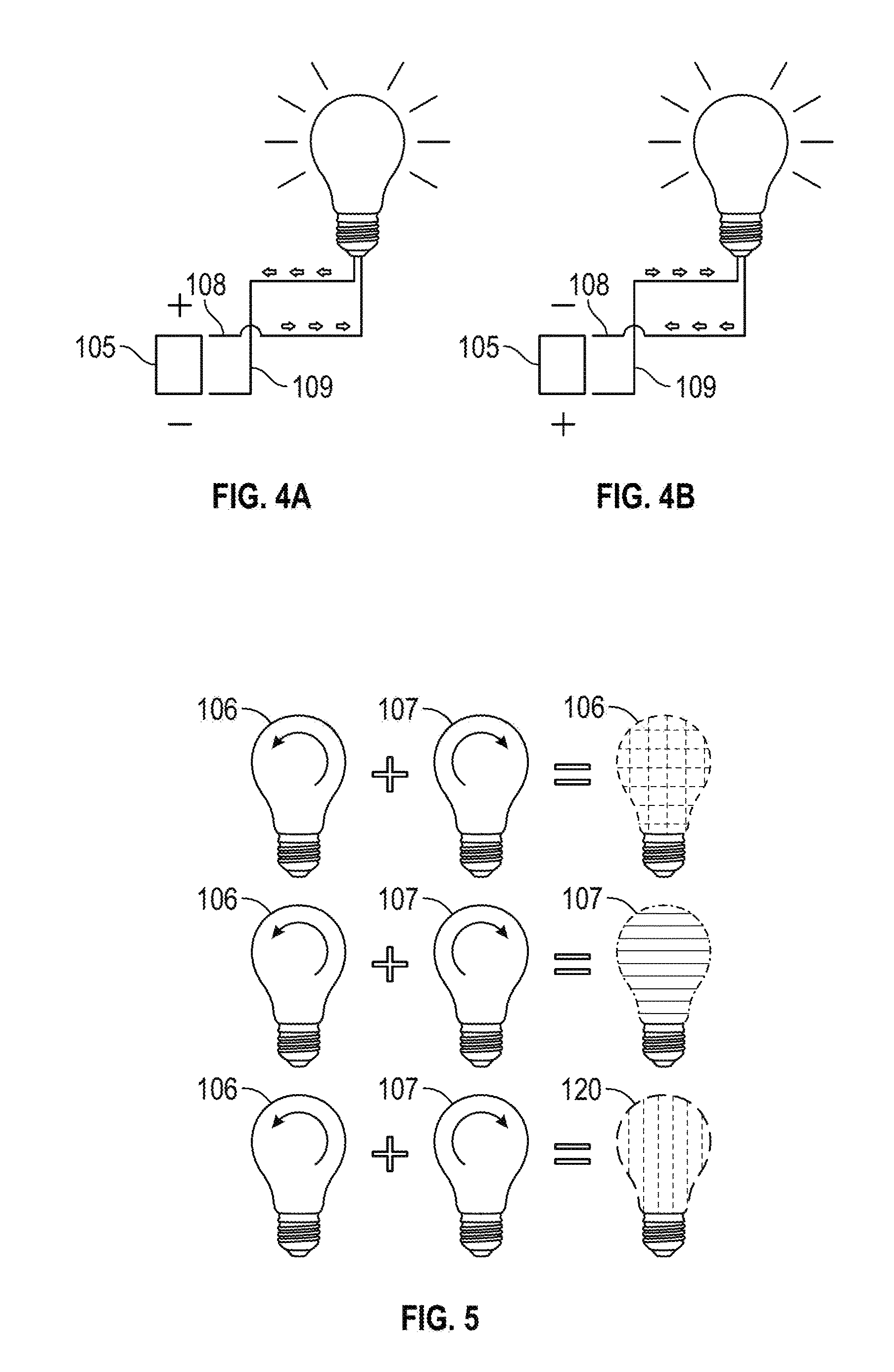
The invention is a lighting system that uses LEDs to create a unique lighting effect. The system consists of two strings of LEDs that produce different colored light. These strings are activated alternately to create a combined light with a different color than each string. The light is created quickly and can be difficult to detect with the naked eye. The technical effect of this invention is a unique and unexpected lighting effect that can create a buzz or special atmosphere.

Problems solved by technology

However, current does not flow easily in the reverse direction.
Operating connected lighting in this manner creates inefficiency.
Indeed, it is known in the art that power supply failure is one of the most common modes of LED bulb failure.
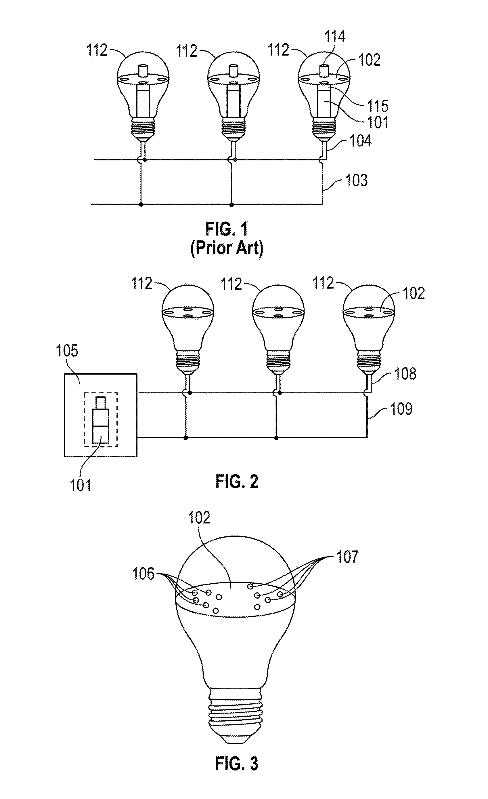
Another inefficiency found in modern LED connected lighting technology is that delivered current only operates one LED string within each bulb 112.

Method used


Image

  • Systems and methods for optimizing power and control of a multicolored lighting system
  • Systems and methods for optimizing power and control of a multicolored lighting system
  • Systems and methods for optimizing power and control of a multicolored lighting system

Examples


Embodiment Construction

[0027]The present invention will now be described more fully hereinafter with reference to the accompanying drawings, in which preferred embodiments of the invention are shown. This invention may, however, be embodied in many different forms and should not be construed as limited to the embodiments set forth herein. Rather, these embodiments are provided so that this disclosure will be thorough and complete, and will fully convey the scope of the invention to those skilled in the art. Those of ordinary skill in the art realize that the following descriptions of the embodiments of the present invention are illustrative and are not intended to be limiting in any way. Other embodiments of the present invention will readily suggest themselves to such skilled persons having the benefit of this disclosure. Like numbers refer to like elements throughout.

[0028]Although the following detailed description contains many specifics for the purposes of illustration, anyone of ordinary skill in th...


PUM


Abstract

Embodiments of the present invention are related to a lighting system comprising a control unit that manages a lighting device with an LED board within an optical chamber. The LED board includes a first string of LEDs and a second string of LEDs. The control unit and the LED board are configured to electrically couple to first and second wires. The first string of LEDs and the second string of LEDs are configured to emit light having different spectral power distributions within the visible spectrum. The first string of LEDs is oriented in an electrically opposite direction than the second string of LEDs. The control unit comprises a switch configured to direct current between the first wire and second wire. The wire to which current is directed is designated active. The designated active wire activates one of the first string of LEDs and second string of LEDs.

Description

RELATED APPLICATIONS[0001]This application claims the benefit under 35 U.S.C. §119(e) of U.S. Provisional Patent Application Ser. No. 62 / 192,380 titled Systems and Methods of Lighting and Control the entire contents of which are incorporated herein by reference.FIELD OF THE INVENTION[0002]The present invention relates to systems and methods for optimizing power and control of a multicolored lighting system.BACKGROUND[0003]Standard connected lighting as depicted in FIG. 1 and found in the prior art, includes a plurality of bulbs 112 with two power supply lines connected thereto. A first power supply line, defined as an active line 103 provides a forward biasing electrical current in a direction toward the bulb 112. A second power supply line, defined as a neutral line 104 accommodates little to no current directed away from the bulb 112. Customary light emitting diode (LED) technology involves using individual bulbs 112 that act as housing for an antenna 114, a radio 115, a power sup...

Claims


Application Information

Patent Timeline
IPC IPC(8): H05B33/08F21V3/02F21V19/00F21K9/232H05B37/02F21K9/235H05B44/00
CPCH05B33/0863H05B37/0281H05B33/0815H05B37/0272F21K9/235F21Y2113/13H05B33/0845F21K9/232F21V3/02F21Y2115/10F21V19/006F21S2/00H05B45/20H05B45/42
Inventor BECK, JOHNIRVIN, JULIABOOMGAARDEN, MARK
Owner LIGHTING SCI GROUP
Learn More