Turbine housing

Active Publication Date: 2017-01-26
CUMMINS LTD WEST YORKSHIRE
View PDF40 Cites 13 Cited by
  • Summary
  • Abstract
  • Description
  • Claims
  • Application Information

AI Technical Summary

Benefits of technology

[0017]It is one object of the disclosure to obviate or mitigate at least one of the aforesaid disadvan

Problems solved by technology

However, the creation of back pressure by the variable geometry turbine can impair the operating performance of the internal combustion engine.
However, problems can arise in the region of the tongue tip.
This can lead to a sudden change in the A/r and therefore in the swirl angle.
This, in turn, can reduce the efficiency of the turbine (for instance by inducing vibration of the turbine wheel) and/or lead to premature failure (for instance from fatigue

Method used


Image

  • Turbine housing
  • Turbine housing
  • Turbine housing

Examples


first embodiment

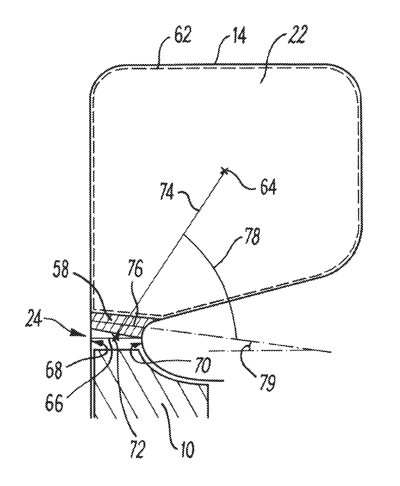
[0091]FIG. 4 shows a cross-section of an inlet volute 14 according to the disclosure. The volute of FIG. 4 is the same as the volute of FIG. 3 with the exception of the configuration of the tongue, therefore only the differences will be discussed here.

[0092]In this embodiment, the tongue tip 58 has been adjusted so that its lateral centerline 76 is no longer parallel to the turbine axis (not shown, but horizontal from the perspective of FIG. 4), but is at an angle 79 of 8° to it. The angle 78 between the lateral centerline 76 of the tongue tip 58 and the line of passage offset 74 is now 64°. This increase in the angle 78 between the tongue tip 58 and line of passage offset 74 reduces the magnitude of the change in A / r across the tongue tip. In addition, this change in angle of the tongue tip 58 decreases its cross sectional area (from the perspective of FIG. 4, the right hand lateral end of tongue tip 58 has been moved downwards towards the throat, shortening the overall lateral wid...

second embodiment

[0095]In the second embodiment, the turbine housing 12 has an additional volute 14′ with an additional volute passage 22′ separated from the volute passage 22 by a dividing wall 86. The additional volute 14′ also has an additional throat 24′ and an additional tongue with an additional tongue tip 58′. The additional tongue tip 58′ has a lateral centerline 76′. The features of the additional inlet volute 14′ have equivalent structure and function to those of the inlet volute 14. The two volute passages 22, 22′ meet at an inlet passage 87 positioned immediately radially outwards from the turbine wheel 10. In this embodiment, the volute passage 22 and the additional volute passage 22′ are both inclined from the radial direction. More particularly, in this case both passages 22, 22′ are inclined from the radial direction in the same axial direction—both are inclined to the right from the perspective of FIG. 6. This may provide an advantageous amount of space to the other axial side of th...

fourth embodiment

[0107]The tongue tip lateral centerline 76 meets the first wall 102 of the throat 24 at an angle of around 90 degrees, and also meets the second wall 104 of the throat at an angle of around 90 degrees. Accordingly, the sum of the angle at which the tongue tip lateral centerline 76 intersects the first wall 102, and the angle at which the tongue tip lateral centerline intersects the second wall 104, is around 180 degrees. The additional tongue tip lateral centerline 76′ meets the first wall 102′ of the additional throat 24′ at an angle of around 78 degrees, and meets the second wall 104′ of the additional throat 24′ at an angle of around 78 degrees. Therefore, the sum of the angle at which the additional tongue tip lateral centerline 76′ intersects the first wall 102′, and the angle at which the additional tongue tip lateral centerline intersects the second wall 104′, is around 156 degrees. Although in this case the tongue tip lateral centerline 76 meets both walls 102, 104 at substa...


PUM


Abstract

A turbine housing has a cavity that defines a turbine axis, and has a volute. The volute comprises a volute passage spiralling radially inwards towards the cavity, a substantially annular throat positioned around the cavity between it and the volute passage, and a tongue terminating at a distal tongue tip. In a plane containing the turbine axis and the tongue tip, the throat defines a line of minimum clearance, the volute passage and tongue tip co-operatively define a preliminary inlet area, and the tongue tip defines a tongue tip lateral centerline. The line of minimum clearance and the preliminary inlet area co-operatively define a line of passage offset, which connects the centroid of the preliminary inlet area and a point half way along the line of minimum clearance. The line of passage offset is not perpendicular to the turbine axis, and the tongue tip lateral centerline and the line of passage offset define an angle therebetween of at least 60 degrees.

Description

RELATED APPLICATIONS[0001]The present application is a National Stage Application under 35 USC §371 of PCT Application No. PCT / GB2014 / 053693, filed Dec. 12, 2014, which claims priority to U.K. Application No. 1322206.2, filed Dec. 16, 2013, the entire disclosures of which being hereby incorporated herein by reference.TECHNICAL FIELD[0002]The present disclosure relates to a turbine housing for a turbine assembly, and has particular, but not exclusive, application to turbochargers.BACKGROUND[0003]Turbochargers are well known devices for supplying air to the intake of an internal combustion engine at pressures above atmospheric (boost pressures). A conventional turbocharger comprises an exhaust gas driven turbine wheel, mounted on a rotatable shaft, within a turbine housing. Rotation of the turbine wheel rotates a compressor wheel, mounted on the other end of the shaft, within a compressor housing. The compressor wheel delivers compressed air to the engine intake manifold. The turbocha...

Claims


Application Information

Patent Timeline
IPC IPC(8): F01D9/02F01D25/24F02B37/00
CPCF01D9/026F02B37/00F05D2250/38F05D2220/40F01D25/24Y02T10/12
Inventor HUGHES, STEPHEN
Owner CUMMINS LTD WEST YORKSHIRE
Why Eureka
Try Eureka