Driver Behavior Monitoring

a technology for driving behavior and monitoring systems, applied in the direction of machine-to-machine/machine-type communication services, instruments, transportation and packaging, etc., can solve the problems of not being able to detect the first trailing vehicle, and frequent hard stopping

Active Publication Date: 2017-01-26
LINDSAY JOHN
View PDF17 Cites 145 Cited by
  • Summary
  • Abstract
  • Description
  • Claims
  • Application Information

AI Technical Summary

Benefits of technology

[0010]Exemplary embodiments of the present invention are directed to a system for monitoring, recording, and analyzing driver activity. An exemplary system comprises a sensor module configured to receive data from one or more sensors that measure acceleration or deceleration associated with a vehicle. A stop detection module is configured to receive the sensor module data, process the sensor module data, and determine an abrupt acceleration or deceleration event. A location module is configured to retrieve the location of the vehicle simultaneous with an abrupt acceleration or deceleration event. The system stores the location of the abrupt acceleration or deceleration event in an event record in an event database.

Problems solved by technology

In such situations, alerting vehicles outside the signaling vehicle's lane of travel would result in false alerts to those other vehicles.
Even where there is no intervening vehicle, it may not be possible for the first trailing vehicle's 2 driver to see the signal lights of a vehicle directly in front of the driver under poor visual conditions such as fog or heavy rain.
These problems are exaggerated in congestion zones or peak driving times, leading to frequent hard stopping, frequent acceleration, and a poor driving experience.
At a minimum, this style of driving is wasteful and uneconomic.

Method used


Image

  • Driver Behavior Monitoring
  • Driver Behavior Monitoring
  • Driver Behavior Monitoring

Examples


Embodiment Construction

[0024]Detailed descriptions of the preferred embodiment are provided herein. It is to be understood, however, that the present invention may be embodied in various forms. Therefore, specific details disclosed herein are not to be interpreted as limiting, but rather as a basis for the claims and as a representative basis for teaching one skilled in the art to employ the present invention in virtually any appropriately detailed system, structure, or manner.

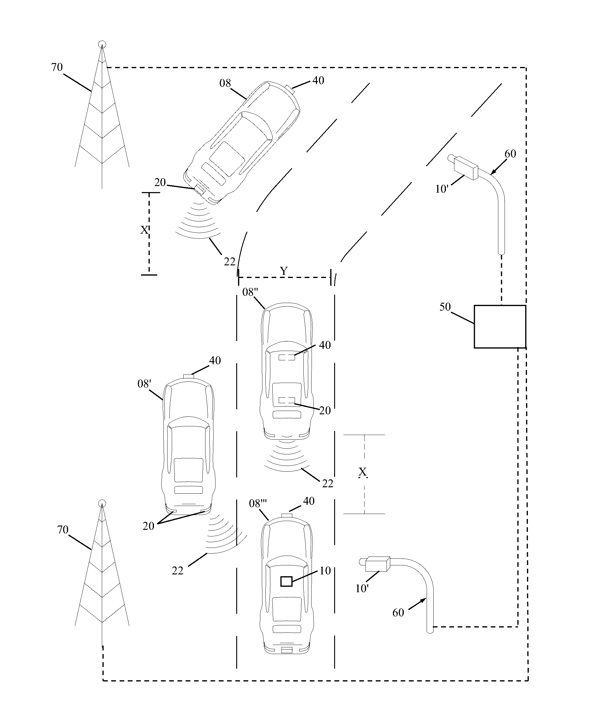
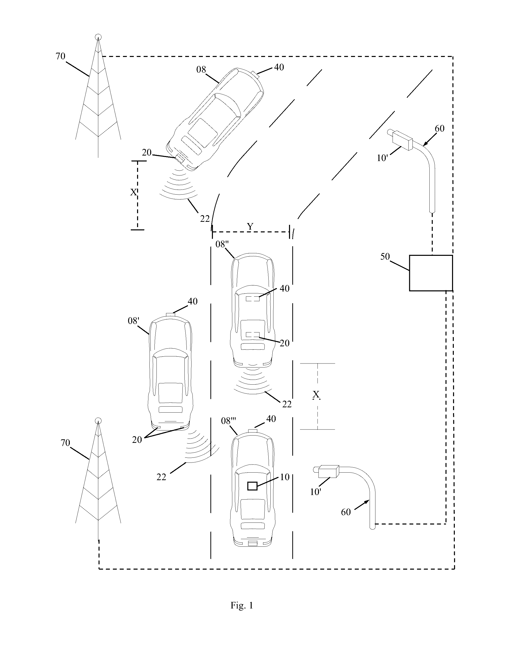
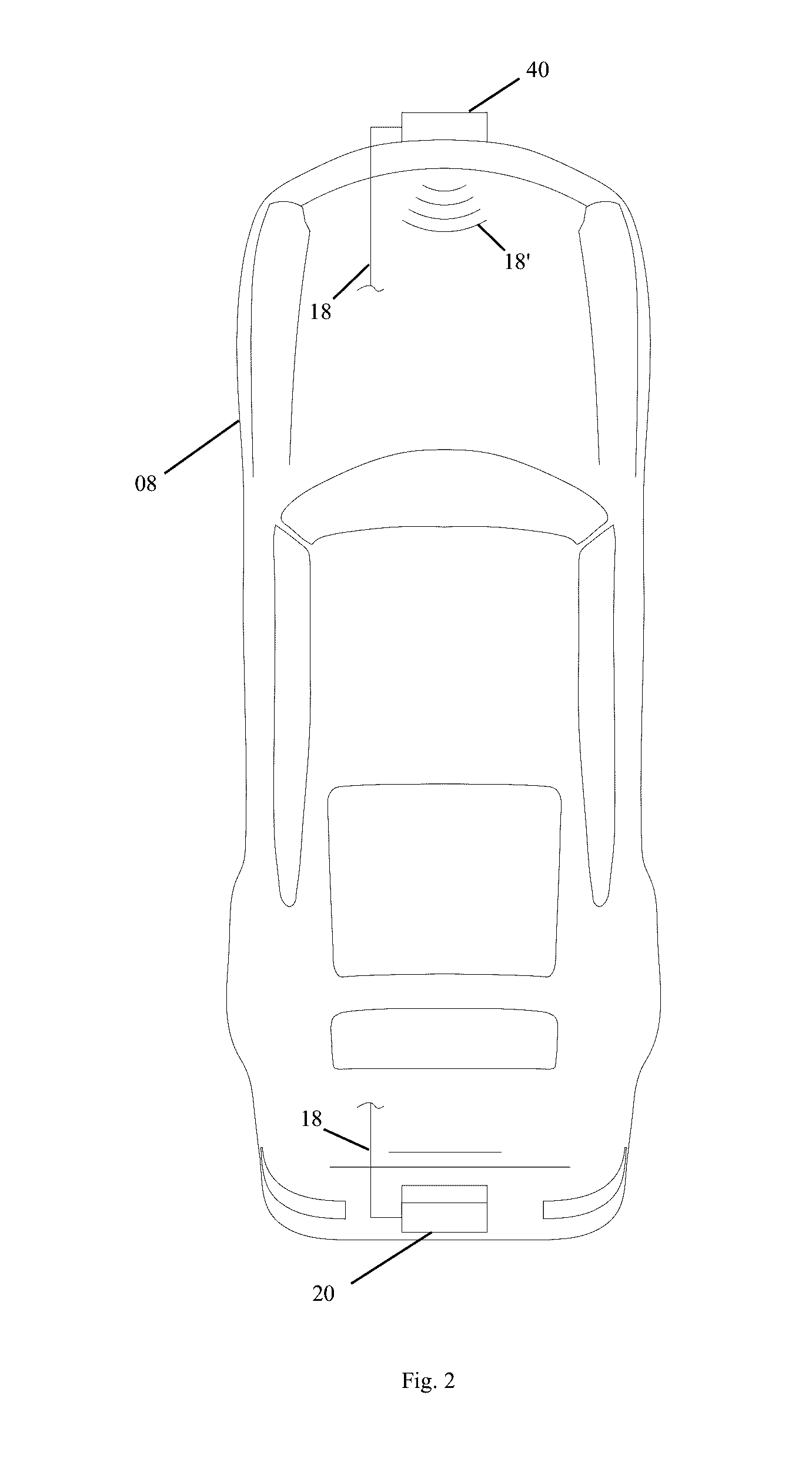
[0025]The current invention relates to a device for directed vehicle to vehicle communication. A representative scenario is relaying a vehicle's signal condition to trailing vehicles in the same lane. FIG. 1 illustrates a plurality of vehicles 08 equipped with vehicle to vehicle communication systems 10 (shown separately in FIG. 3) as they may exist in operation. The vehicle to vehicle communication system 10 includes an emitter 20 and a receiver 40 for attachment to a single vehicle 08. As shown, the emitter 20 and receiver 40 can ...


PUM


Abstract

Exemplary embodiments of the present invention are directed to a system for monitoring, recording, and analyzing driver activity. An exemplary system comprises a sensor module configured to receive data from one or more sensors that measure acceleration or deceleration associated with a vehicle. A stop detection module is configured to receive the sensor module data, process the sensor module data, and determine an abrupt acceleration or deceleration event. A location module is configured to retrieve the location of the vehicle simultaneous with an abrupt acceleration or deceleration event. The system stores the location of the abrupt acceleration or deceleration event in an event record in an event database.

Description

PRIORITY[0001]The present invention claims priority to U.S. patent application Ser. No. 14 / 710,553, which has a filing date of May 12, 2015. U.S. patent application Ser. No. 14 / 710,553 claims priority to PCT patent application PCT / US2014 / 030086, which has a filing date of Mar. 15, 2014. PCT patent application PCT / US2014 / 030086 claims priority to provisional application 61 / 792,148, which has a filing date of Mar. 15, 2013. PCT patent application PCT / US2014 / 030086 claims priority to provisional application 61 / 825,068, which has a filing date of May 19, 2013.BACKGROUND[0002]Field of the Invention[0003]The present invention relates to vehicle activity monitoring systems, more specifically to systems for monitoring, recording, and analyzing vehicle activity.[0004]Description of the Related Art[0005]For certain driving conditions, communications from one vehicle to a subset of other proximate vehicles is desirable. Two such example situations are a braking or turn signal usage. In such si...

Claims


Application Information

Patent Timeline
Patent Type & Authority Applications(United States)
IPC IPC(8): G07C5/02G08G1/127G01C21/26G01S19/01G01C21/16
CPCG07C5/02G01S19/01G08G1/127G01C21/26G01C21/16G08G1/096791H04B10/1129G08G1/0962G08G1/096716G08G1/096758G08G1/162G08G1/165G08G1/166G08G1/22H04W84/005H04W84/18H04L67/00H04W4/70H04W4/027H04W4/029H04W4/40B60W40/10
Inventor LINDSAY, JOHN
Owner LINDSAY JOHN
Why Eureka
Try Eureka