Vaporizer With Multiple-Chamber Heating

Inactive Publication Date: 2017-02-02
CLOUD V ENTERPRISES
View PDF7 Cites 57 Cited by
  • Summary
  • Abstract
  • Description
  • Claims
  • Application Information

AI Technical Summary

Benefits of technology

[0008]The present invention, or more accurately the preferred embodiment of the present invention, provides a compact vaporizer comprising a multiple-chamber atomizer that allows a user to control the volume of a substance to be vaporized, and ensures contact between a heating coil and all of the substance loaded into the atomizer by the user. The atomizer comprises an upper chamber and a lower chamber disposed below the upper chamber. At the bottom of the upper chamber, a funnel directs the substance to the lower chamber, and specifically to the heating coil disposed within the lower chamber. The substance is controllable heated when in the upper chamber by one or more heating elements disposed on the outside of the upper chamber, so as to reduce the viscosity of the substance. The diameter of the funnel opening is such that high viscosity liquids and suspensions, such as oil and wax, only pass through the funnel to the lower chamber when they are heated. In this manner, the volume of the substance passing to the heating coil in the lower chamber can be cont

Problems solved by technology

While a wick may be suitable to control the flow of a low viscosity liquid material, such as e-juice, to the heating coil of an atomizer, a wick is not capable of transporting a hi

Method used


Image

  • Vaporizer With Multiple-Chamber Heating
  • Vaporizer With Multiple-Chamber Heating
  • Vaporizer With Multiple-Chamber Heating

Examples


Embodiment Construction

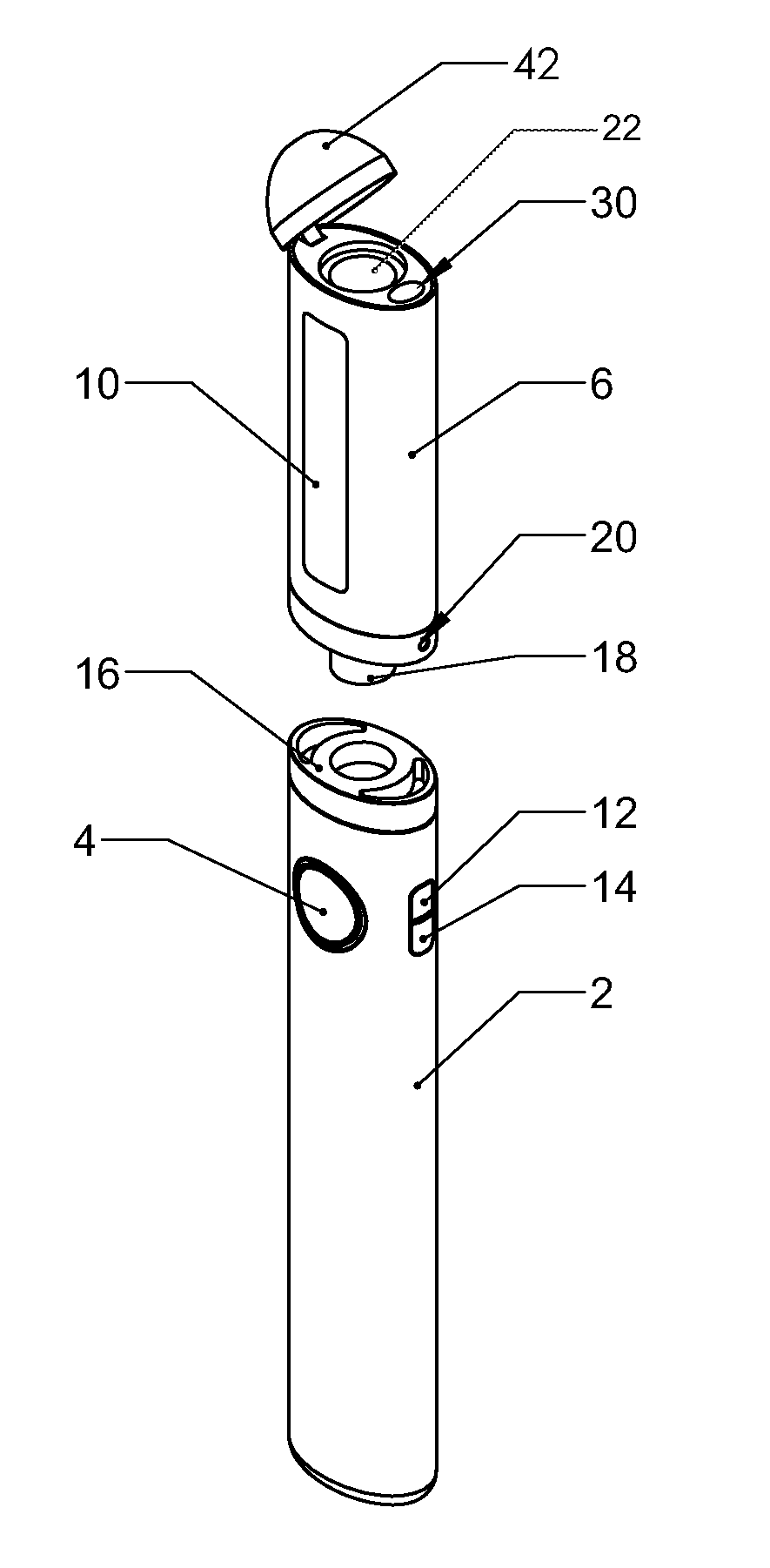
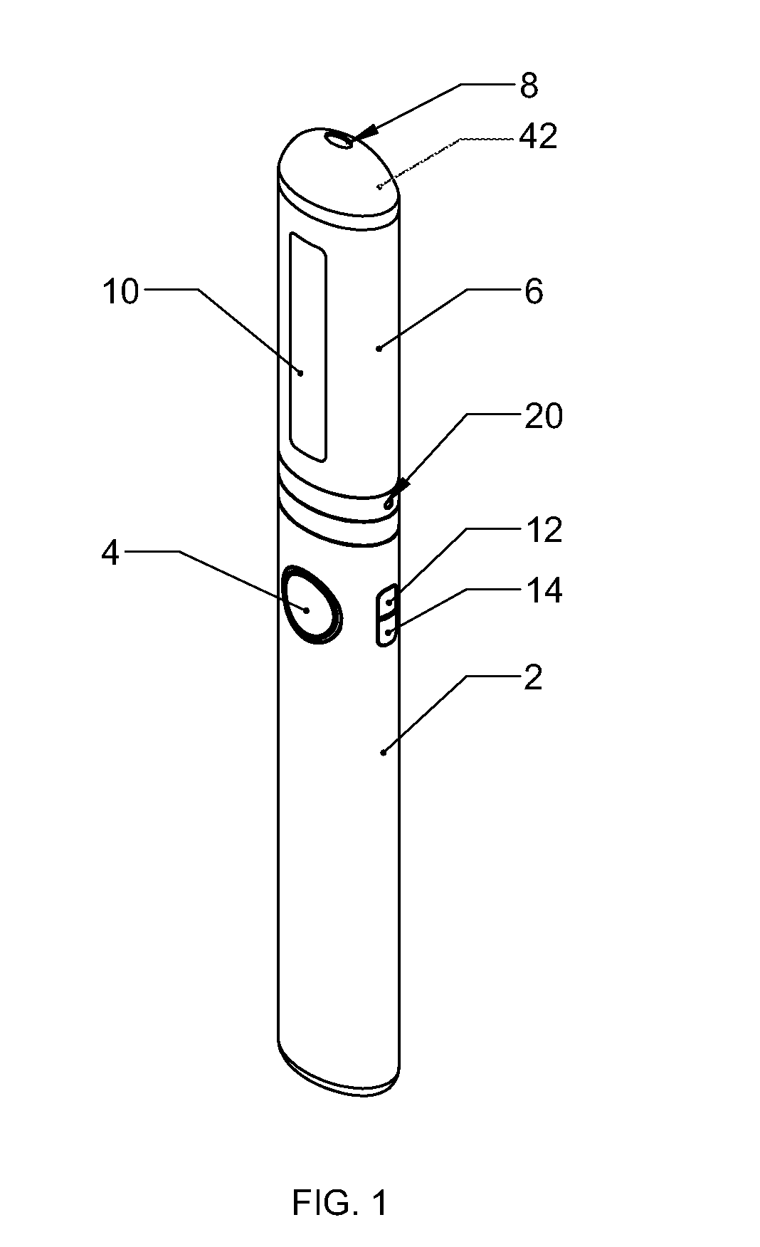
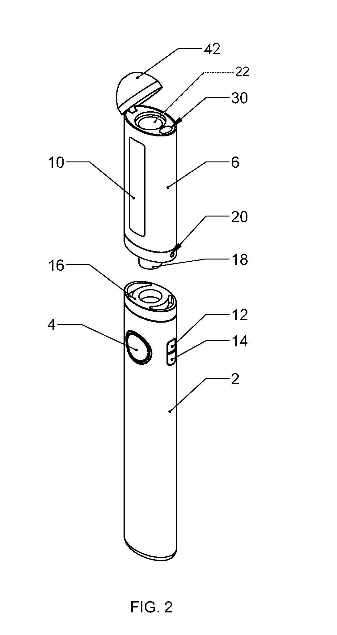
[0014]As depicted in FIG. 1, the preferred embodiment compact vaporizer includes a battery housed within a battery casing 2 and a mouthpiece 6. Disposed on the battery casing is a large button 4 that enables a user to activate a heating coil (discussed below). Two additional buttons, the tank heater button 12 and funnel heater button 14, are also disposed on the battery casing 2. As discussed more fully below, activation of the tank heater button 12 heats the outside of the tank where material is loaded into the compact vaporizer, and activation of the funnel heater button 14 heats the outside of the funnel disposed immediately below the tank where material is loaded.

[0015]The mouthpiece 6 has a clear window 10 that allows the user to view the inner workings of the components within the mouthpiece 6. Through the window 10, the user can see how much of the substance to be vaporized remains in the tank, and, preferably, also how much of the substance to be vaporized is in the funnel.

[...


PUM


Abstract

A vaporizer comprising a mouthpiece and battery. The mouthpiece preferably includes a loading chamber, a funnel disposed directly below the loading chamber, and an atomizer disposes directly below the funnel. The atomizer includes a heat source connected to the battery for vaporizing a substance desired to be inhaled. The loading chamber and funnel are each connected to heating elements, electrically connected to the battery, for heating a substance located in the loading chamber or funnel, respectively. An air pathway is provided within the mouthpiece that allows a user to inhale a substance vaporized in the atomizer after it travels through the loading chamber and funnel.

Description

BACKGROUND OF THE INVENTION[0001]1. Field of the Invention[0002]The present invention relates generally to the field of vaporizers used to heat solids, liquids and suspensions, such as waxes and oils, for inhalation by a user.[0003]2. Prior Art[0004]Vaporizers, including electronic cigarettes, have become increasingly popular over the past ten years. As consumers have become more aware of the health consequences of inhaling smoke produced by combusting tobacco and other substances, vaporizers have become a healthier alternative to cigarettes, cigars, pipes and other smoking implements. While some vaporizers are large and bulky—sometimes intended to mimic the aesthetic look of a hookah—most vaporizers are small enough to fit into a user's pocket or purse for convenience.[0005]The typical configuration of a compact vaporizer includes a battery electrically connected to an atomizer housed within the vaporizer. The solid, liquid or suspension material sought to be vaporized is placed in...

Claims


Application Information

Patent Timeline
IPC IPC(8): A24F47/00H05B3/44H05B1/02A24F40/46A24F40/51A24F40/60
CPCA24F47/008H05B3/44H05B1/0297H05B1/0227A24F40/46A24F40/51A24F40/60
Inventor EKSOUZIAN, VAHAN
Owner CLOUD V ENTERPRISES
Why Eureka
Try Eureka