
Dynamic segregation monitoring of concrete

a technology of segregation monitoring and concrete, applied in the field of manufacture and processing of concrete, can solve the problems of concrete segregation, weak, porous, non-durable structure, job delays and cost increases,

Active Publication Date: 2017-02-02
VERIFI
View PDF0 Cites 33 Cited by
  • Summary
  • Abstract
  • Description
  • Claims
  • Application Information

AI Technical Summary

Benefits of technology

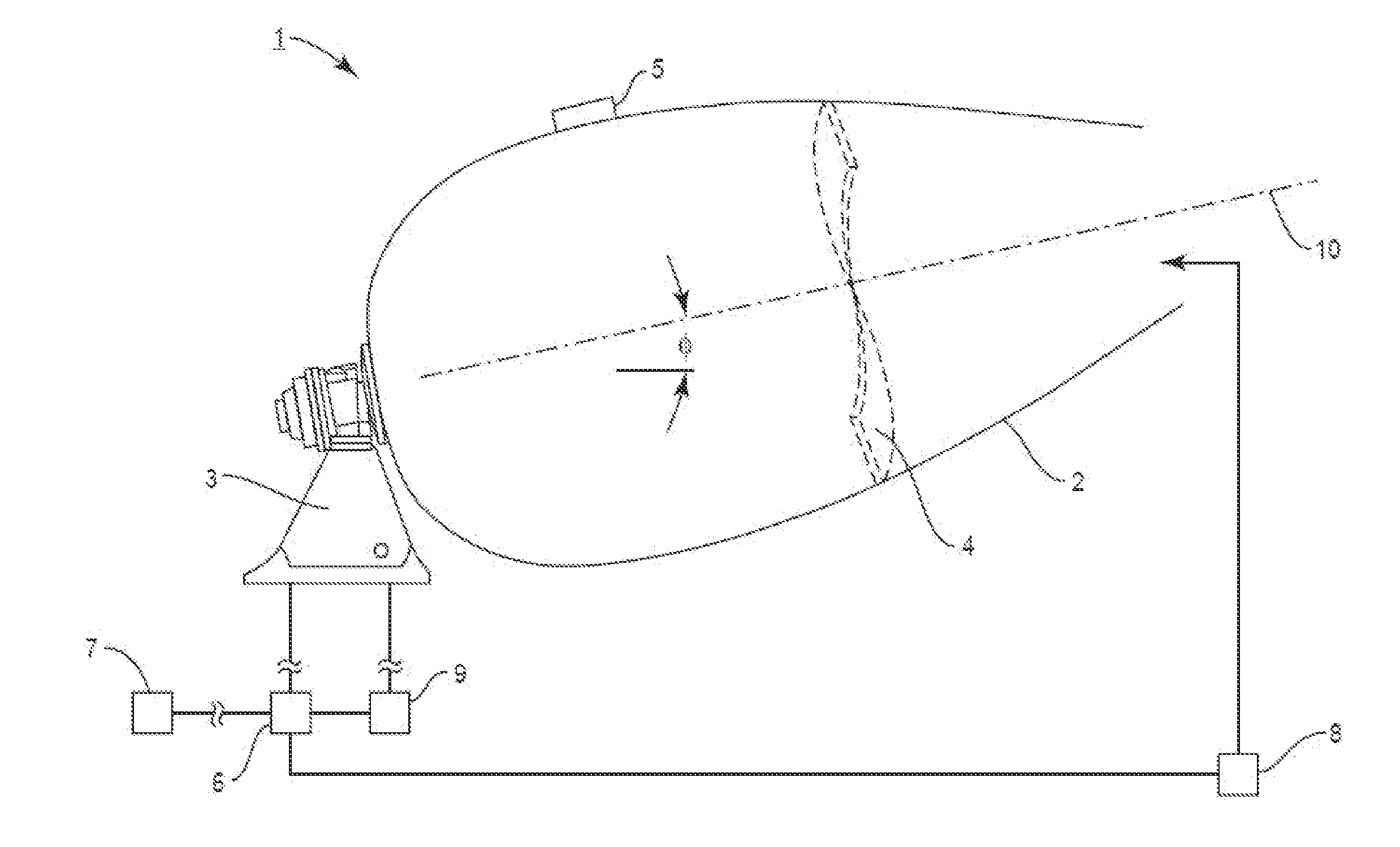
The present invention provides a system and method for monitoring dynamic segregation in concrete in real-time using a rotating mixer drum. The system measures various rheology parameters of the concrete as it rotates and detects changes in these parameters that indicate segregation. The system can deploy a first dynamic segregation detection protocol and a second dynamic segregation detection protocol, which can help to confirm the presence of segregation and take appropriate action, such as alerts, changing the mixer drum rotation rate, or adding chemical admixtures to mitigate segregation. The system can also continuously monitor the concrete rheology parameter to detect any changes in segregation in real-time and initiate appropriate actions to prevent further segregation.

Problems solved by technology

Improper aggregate grading, aggregate shape, and other factors may cause concrete to become segregated, and such factors may arise outside of the knowledge of the concrete manufacturer.
Segregation can cause the concrete to be rejected at the job site, or, if such a segregated concrete is poured and placed at the job site, the hardened concrete is likely to result in a weak, porous, and non-durable structure.
In serious cases, concrete that has segregated but has been placed will need to be removed and replaced, causing job delays and cost increases.
If the materials are known in advance to be susceptible to this problem, the mix designer can exercise greater care in selection and proportioning of ingredients, but day-to-day variations in raw material and mixing behavior can result in undetected segregation occurrences and serious consequences.

Method used


Image

  • Dynamic segregation monitoring of concrete
  • Dynamic segregation monitoring of concrete
  • Dynamic segregation monitoring of concrete

Examples


Embodiment Construction

[0033]The present invention now will be described more fully hereinafter with reference to the accompanying drawings, in which various exemplary embodiments are shown illustrating variations within the scope of the invention. This disclosure may, however, be embodied in many different forms and should not be construed as limited to the embodiments set forth herein; rather, these embodiments are provided so that this disclosure will be thorough and complete and fully convey the scope of the invention to those of ordinary skill in the art.

[0034]The term “cement” as used herein includes hydratable cement such as Portland cement which is produced by pulverizing clinker consisting of hydraulic calcium silicates, aluminates and aluminoferrites, and one or more forms of calcium sulfate (e.g., gypsum) as an interground additive. Portland cement may be combined with one or more supplemental cementitious materials, such as fly ash, granulated blast furnace slag, limestone, natural pozzolans, ...


PUM

PropertyMeasurementUnit
rheologyaaaaaaaaaa
hydraulic pressureaaaaaaaaaa
constant rotation speedaaaaaaaaaa

Abstract

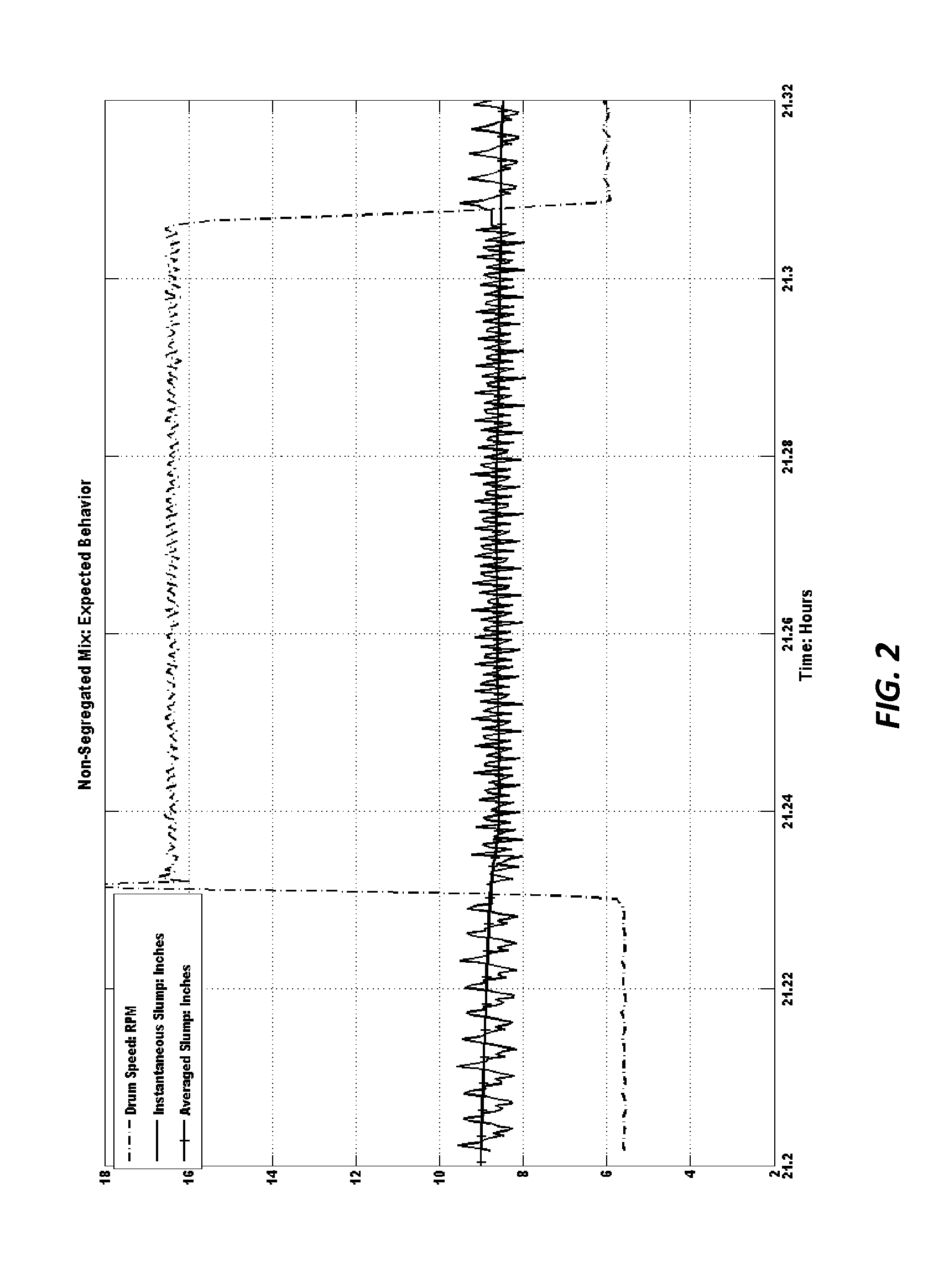
A system and process for detecting dynamic segregation in concrete rotated within a mixer drum, such as mounted on a delivery truck. A system processor is programmed to monitor an instantaneous and averaged rheology parameter (e.g., instantaneous and averaged slump values) and to deploy one or more protocols for detecting the occurrence of segregation. A first protocol comprises monitoring the averaged slump or other rheology value of concrete during and immediately after a jump in drum speed of at least plus or minus four rotations per minute and detecting when a change in the averaged slump value meets or exceeds a threshold limit pre-selected by the user or the system processor; and an optional second protocol comprises monitoring the instantaneous slump or other rheology value of the concrete when the mixer drum is rotating at a constant speed for at least three successive rotations.

Description

FIELD OF THE INVENTION[0001]The present invention relates to manufacture and processing of concrete, and more particularly to a monitoring system and process for confirming existence of dynamic segregation in concrete contained in mixer drums such as found on concrete delivery trucks.BACKGROUND OF THE INVENTION[0002]It is known to employ automated systems and processes for monitoring slump and other properties of concrete contained in rotating mixer drums, such as mixer drums that are mounted on concrete delivery trucks. The hydraulic pressure required to rotate the concrete in the mixer drum can be measured by a processor unit on a continuous basis and correlated with the property of the concrete being mixed, and adjustments can be made to the concrete through additions of water or chemical as controlled by the automated system processor unit.[0003]In US 2012 / 0020180 A1 (owned by the same assignee hereof), Koehler et al. taught that variations in the energy or hydraulic pressure mo...

Claims


Application Information

Patent Timeline
Patent Type & Authority Applications(United States)
IPC IPC(8): B28C5/42G05B19/048E01C19/10B28C7/02
CPCB28C5/422B28C7/026G05B2219/42286E01C19/1027E01C19/1063G05B19/048G01N33/383
Inventor JORDAN, RICHARD K.ROBERTS, MARK F.GLINA, YANTREGGER, NATHAN A.ROBERTS, LAWRENCE R.KOEHLER, ERIC P.
Owner VERIFI
Learn More