
Locking Structure for a Bicycle

Inactive Publication Date: 2017-02-02
SHENG YUNG LOCK IND
View PDF2 Cites 10 Cited by
  • Summary
  • Abstract
  • Description
  • Claims
  • Application Information

AI Technical Summary

Benefits of technology

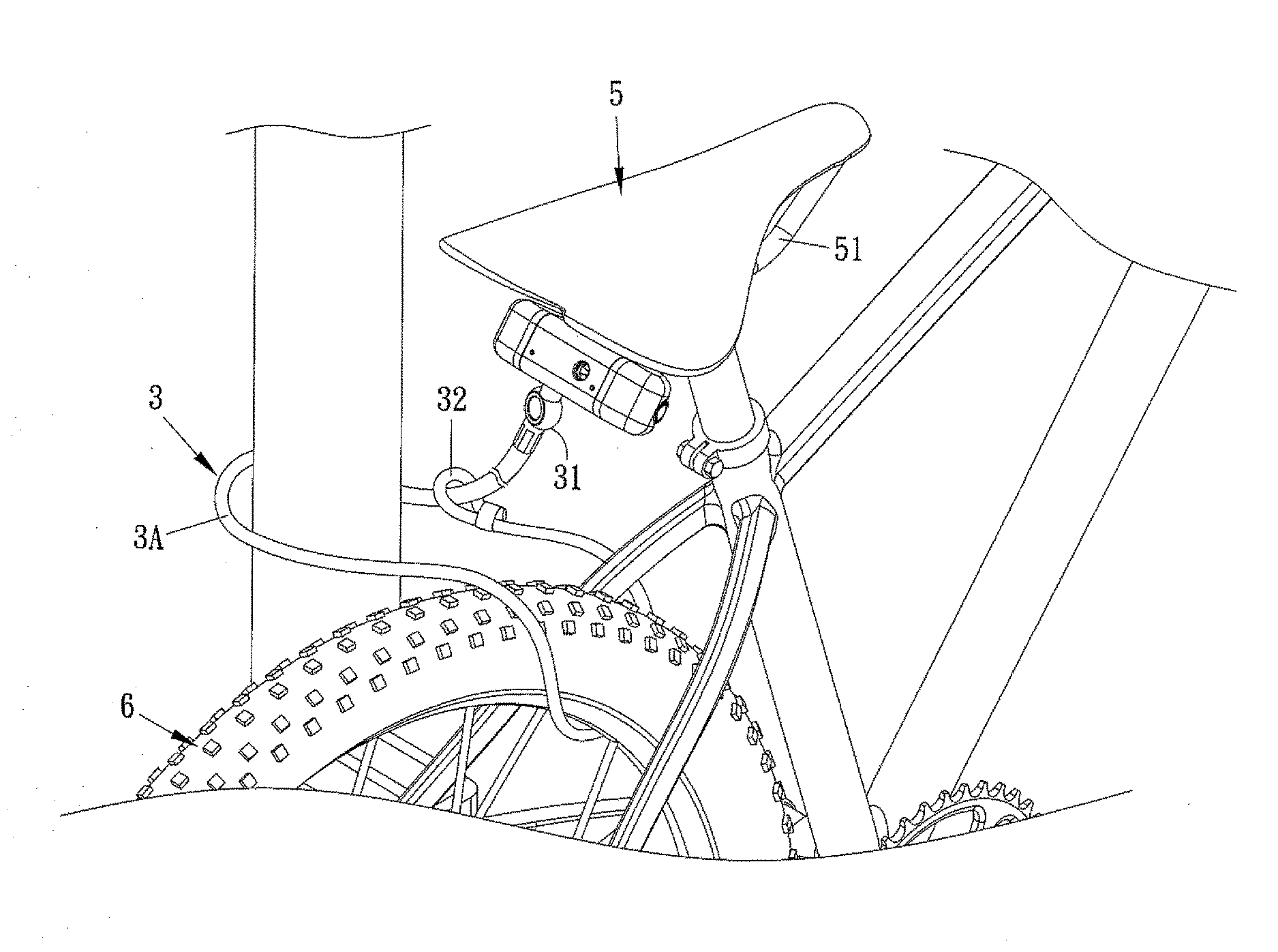
The present invention is a locking structure for bicycles that allows for easy attachment of detachable parts to the bicycle and secure locking. The locking structure includes a flexible strip that surrounds the bicycle's wheels and a fix post to prevent theft. The invention also provides a convenient way to attach and remove the fixing mount from the bicycle while maintaining security. Additionally, the invention connects each light assembly with the locking member, allowing for illumination and aesthetic appeal while enhancing anti-theft performance.

Problems solved by technology

But the bicycle is stolen often after disassembling these detachable parts, so locking the bicycle by way of a bicycle lock is required.
A conventional bicycle lock is portable and merely locks wheels of the bicycle, so it is inconvenient to carry the bicycle lock with user.
To overcome such a problem, a removable bicycle lock has been developed, yet this removable bicycle lock can only lock one of the detachable parts of the bicycle, and the other detachable parts and the bicycle may be stolen, so extra cost for purchasing additional bicycle locks is inevitable.
However, such configuration will occupy installation space and influence aesthetics appearance.
In addition, the light will be stolen.

Method used


Image

  • Locking Structure for a Bicycle
  • Locking Structure for a Bicycle
  • Locking Structure for a Bicycle

Examples


Embodiment Construction

[0031]The present invention will be clearer from the following description when viewed together with the accompanying drawings, which show, for purpose of illustrations only, the preferred embodiment in accordance with, the present invention.

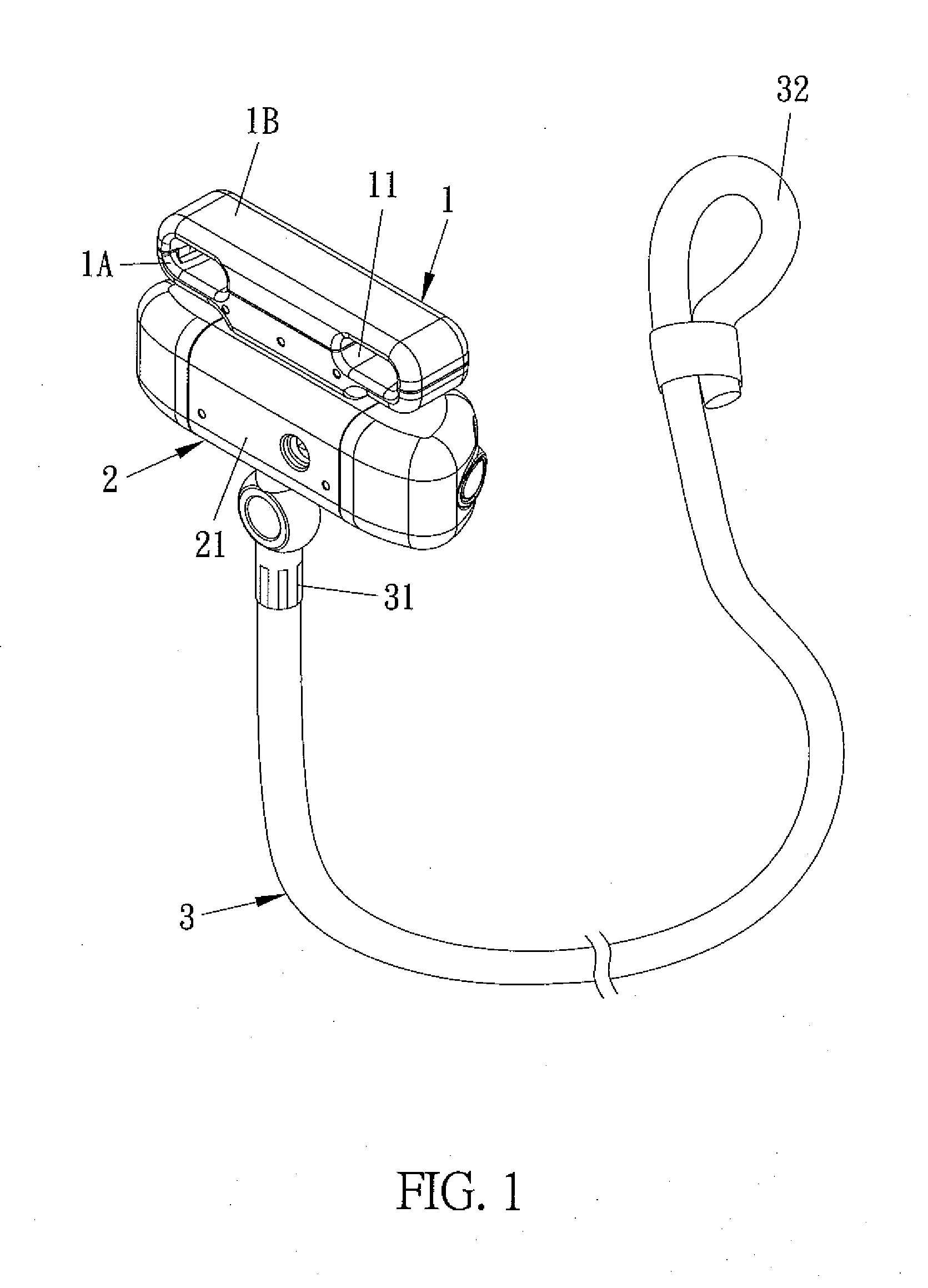
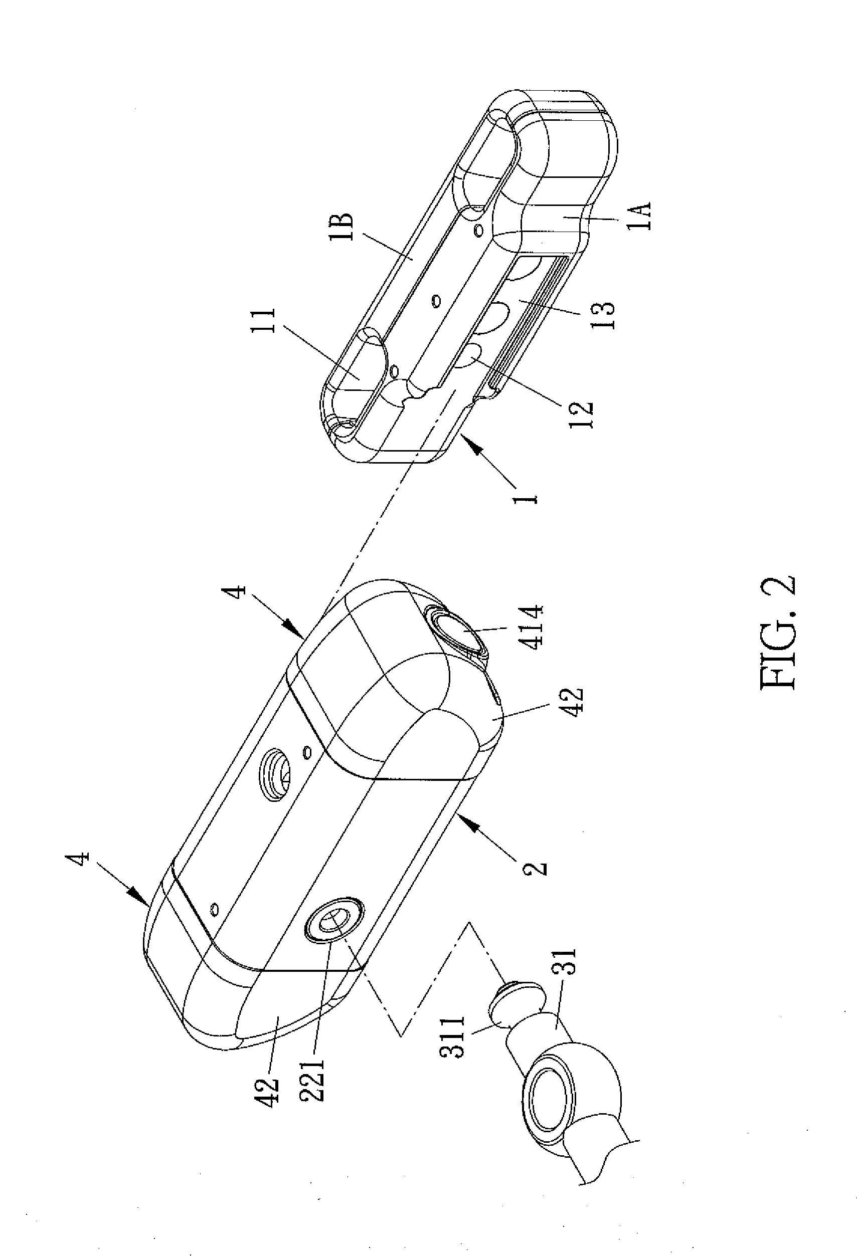
[0032]Referring to FIGS. 1-6, a locking structure for a bicycle according to a preferred embodiment of the present invention comprises: a fixing mount 1, a locking member 2, a flexible strip 3, and two light assemblies 4.

[0033]The fixing mount 1 includes at least one orifice 11, a recessed portion 12, and a first connecting portion 13. In this embodiment, the fixing mount 1 includes two orifices 11, wherein the fixing mount 1 is comprised of a first part 1A and a second part 1B connecting with the first part 1A, and the at least one orifice 11 is defined between the first part 1A and the second part 1B, the recessed portion 12 is arcuate and is formed on the first part 1A, and the first connecting portion 13 is arranged on the first part 1A.

[003...


PUM


Abstract

A locking structure for a bicycle contains: a fixing mount, a locking member, and a flexible strap. The fixing mount includes at least one orifice, a recessed portion, and a first connecting portion. The locking member includes a housing in which a lock block and a retaining unit are accommodated, the housing has a second connecting portion for mating with the first connecting portion, and the lock block has a cylinder core and an aperture. The flexible strap includes a coupling bolt arranged on a first end thereof and a loop disposed on a second end thereof. When the coupling bolt inserts into and locks in the aperture, it pushes the retaining unit into the recessed portion to fix the locking member and the fixing mount together, and the coupling bolt inserts through the loop so that the flexible strip forms a positioning ring.

Description

BACKGROUND OF THE INVENTION[0001]Field of the Invention[0002]The present invention relates to a bicycle lock, and more particularly to a locking structure for a bicycle which is fixed on detachable parts of the bicycle so to avoid theft of the detachable parts and the bicycle, to make alert and illumination.[0003]Description of the Prior Art[0004]Bicycle contains a plurality of detachable parts, such as a seat saddle, a front wheel, and a rear wheel which are connected together and are removed easily for maintenance. But the bicycle is stolen often after disassembling these detachable parts, so locking the bicycle by way of a bicycle lock is required.[0005]A conventional bicycle lock is portable and merely locks wheels of the bicycle, so it is inconvenient to carry the bicycle lock with user. To overcome such a problem, a removable bicycle lock has been developed, yet this removable bicycle lock can only lock one of the detachable parts of the bicycle, and the other detachable parts...

Claims


Application Information

Patent Timeline
IPC IPC(8): B62H5/00E05B67/06E05B71/00B62H5/14E05B45/00E05B17/10B62H5/20E05B67/00E05B41/00
CPCB62H5/14B62H5/001E05B67/003E05B67/063E05B71/00B62H5/006E05B45/005E05B17/10B62H5/003B62H5/20E05B41/00E05B73/0005
Inventor CHEN, LI-YU
Owner SHENG YUNG LOCK IND
Learn More