Tricycle kick scooter

a kick scooter and tricycle technology, applied in the field of kick scooters, can solve the problems of inability to produce a propulsive force by itself, rider may be at risk of being tripped, etc., and achieve the effects of easy management, long storage time, and good looking

Inactive Publication Date: 2017-02-02
MSKI
View PDF0 Cites 8 Cited by
  • Summary
  • Abstract
  • Description
  • Claims
  • Application Information

AI Technical Summary

Benefits of technology

[0024]The present invention has a structure,
[0025]wherein the configuration of a major component operating about an elastic body of a connection part is hidden inside, wherein the elastic body is able to return the vertical frame to its original position after it has been inclined and tilted in the left and right directions,
[0026]whereby the tilting of the vertical frame may be freely carried out, and the vertical frame is able to return to its original position, so there may not be any chance for the human body to contact therewith, whereby it is possible to previously prevent any accident which was likely to happen in the conventional technology.
[0027]Moreover, since the vertical frame is hidden and protected from a predetermined attack from an external environment, for example, rain and wind, dust, etc., the management thereof is easy, and a long time storage is available.
[0028]In addition thereto, since the joint having a relatively complicated configuration is not exposed to the outside, it is possible to manufacture a tricycle kick scooter which visually provide a good looking exterior.
[0029]Furthermore, since a compression elastic body made in a rubber bar type, the manufacturing cost of which is very low, can be directly used after it has been cut into the forms of pieces, so the manufacturing price can be reduced, and the durability of the product can be enhanced since it is manufactured in a relatively simple structure.

Problems solved by technology

The aforementioned patent is not equipped with any configuration to make a propulsive force while spreading the feet of the rider, for which it is impossible to produce a propulsive force by itself.
Since the direction change in the leftward and rightward directions, however, should be carried out in a state where the rotary shaft of a handle stands upward vertically, the rider is not able to have a posture during the change of the direction in order for the rider to withstand the centrifugal force, and the rider's body may be leaned toward the outward direction in case of a cornering action, so the rider may be at risk to be capsized (tumble).

Method used


Image

  • Tricycle kick scooter
  • Tricycle kick scooter
  • Tricycle kick scooter

Examples


Embodiment Construction

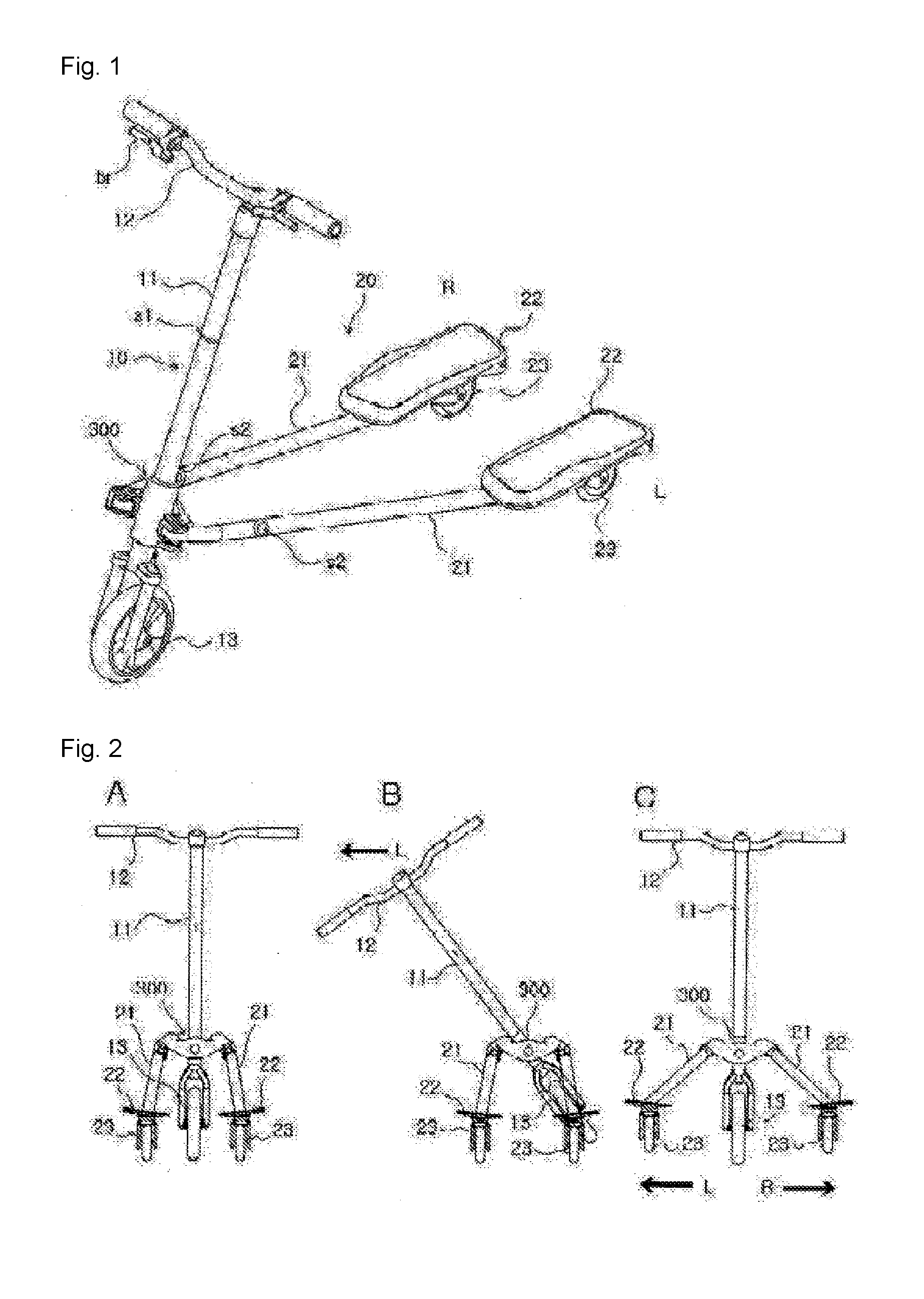
[0044]The tricycle kick scooter may include:

[0045]a vertical frame which is equipped with a handle and a front wheel and stands upright;

[0046]a pair of left and right horizontal frames which are equipped with a foot rest and a rear wheel and are disposed horizontal at a rear side of the vertical frame; and

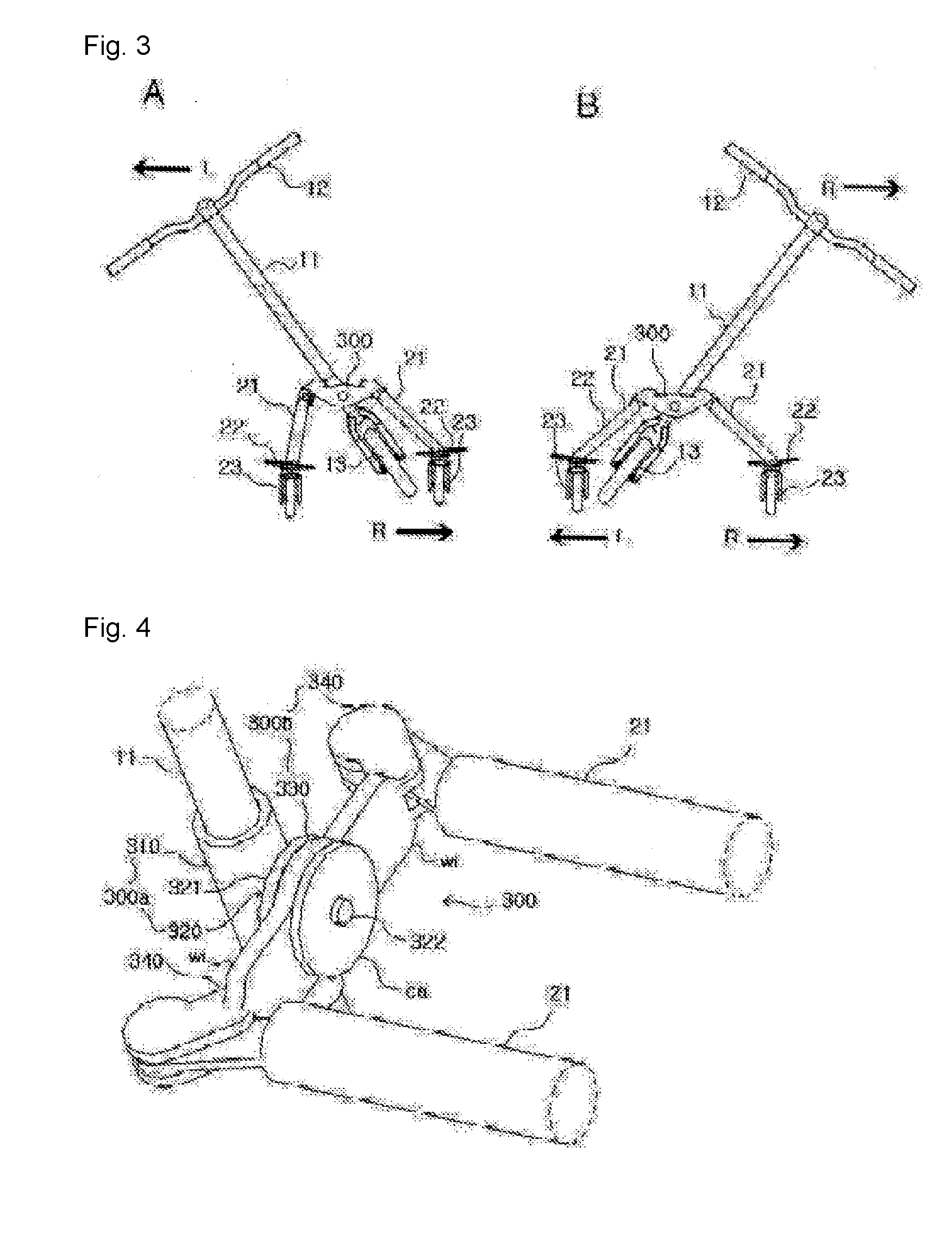
[0047]a connection part which is configured to connect an intermediate portion of the vertical frame and a front end of the horizontal frame,

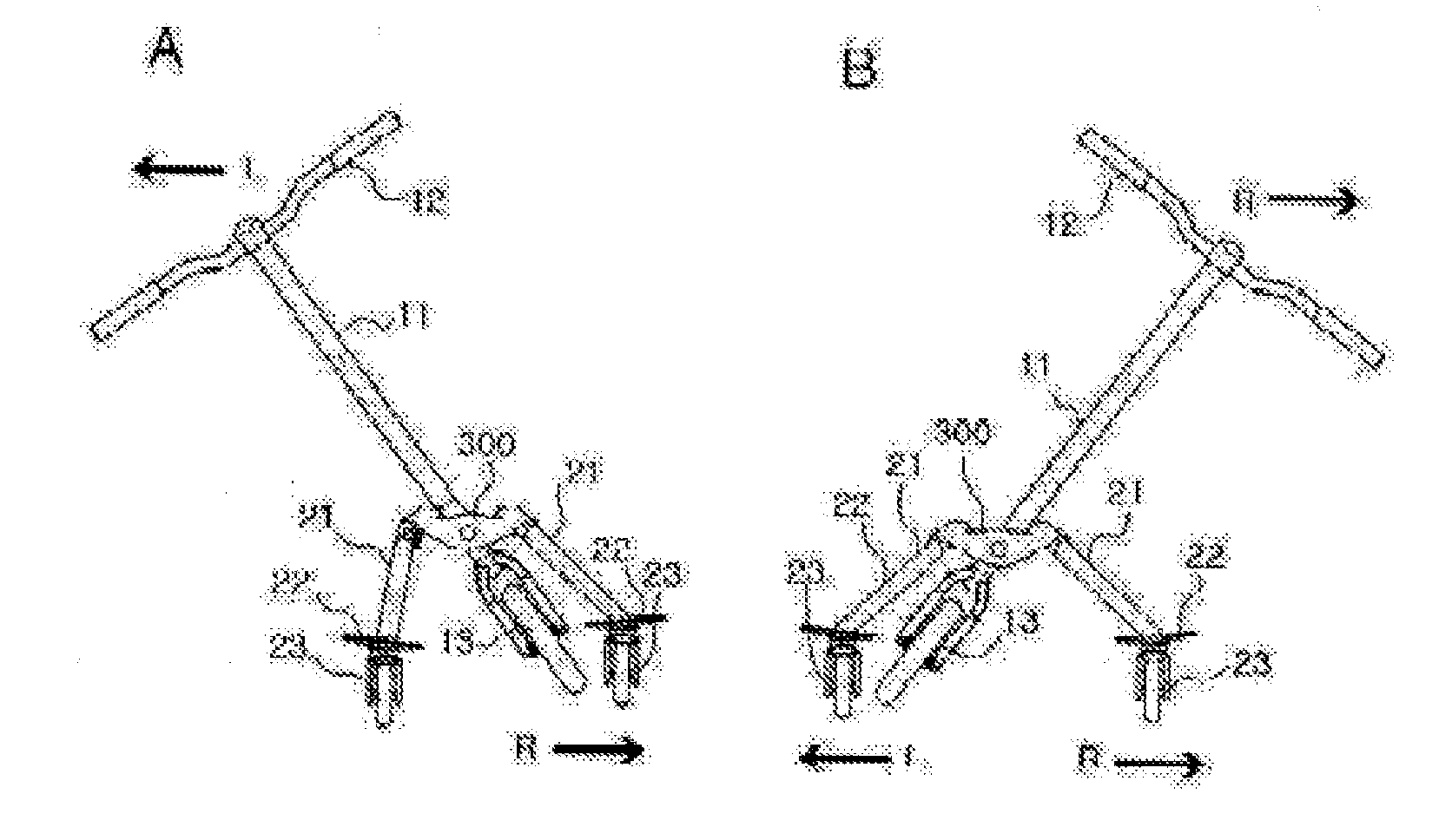
[0048]wherein the kick scooter can be driven in such a way to the horizontal frames are spread out horizontal while simultaneously tilting in the leftward and rightward directions the vertical frame,

[0049]wherein the connection part includes a first unit formed of a vertical frame support tube to which the vertical frame is pivotally engaged; a connection plate the front side of which is attached to a rear end of the vertical frame support tube; a tilting shaft which extends from the center of a rear end of the connection plate to the rear sid...


PUM


Abstract

The present invention relates to a kick scooter (kickboard), which is a kind of human-powered land vehicle. More specifically, the present invention relates to a tricycle kick scooter including one front wheel and two rear wheels, the tricycle kick scooter comprising: a vertical frame; a pair of left and right horizontal frames; and a connection part, wherein the connection part comprises: a vertical frame support pipe; a connection plate; a tilting shaft; a pressing bar; a tilting shaft bearing; a pressing room; a pressing partition; a pressing elastic body; and an unfolding shaft part.

Description

TECHNICAL FIELD[0001]The present invention relates to a kick scooter (a kickboard), which is a kind of a human-powered land vehicle.[0002]More specifically, the present invention relates to a tricycle kick scooter including one front wheel configured to carry out a steering (a direction change), and two rear wheels configured in the form of an inclined caster (or a directional property caster), thus providing a propulsive force.[0003]A rider repeatedly does a spreading action (on the contrary, a narrowing action), thus producing a propulsive force.[0004]In the present invention, the aforementioned device is called a tricycle kick scooter.BACKGROUND ART[0005]As a conventional technology of the present invention, there is the Korean patent laid-open number 46353 (Jun. 12, 2003).[0006]The aforementioned patent is equipped with a configuration and means to incline a rider's body leftward or rightward when changing the riding direction, by which the centrifugal force can be overcome duri...

Claims


Application Information

Patent Timeline
Patent Type & Authority Applications(United States)
IPC IPC(8): B62K5/10B62M1/00B62K5/02B62K21/12B62K5/06
CPCB62K5/10B62K21/12B62M1/00B62K5/02B62K5/06B62K3/002B62K17/00
Inventor KIM, JUNGTAE
Owner MSKI
Why Eureka
Try Eureka