Rigid Bracket Assembly for Mounting a Brake Assembly and Brake Actuator

a bracket assembly and actuator technology, applied in the field of vehicle brakes, can solve the problems of increasing air consumption during braking, and achieve the effects of reducing deflection of the arm, reducing air consumption, and reducing mechanical stress

Active Publication Date: 2017-02-02
BENDIKS SPAJSER FAUNDEJSHN BREJK LLK
View PDF0 Cites 11 Cited by
  • Summary
  • Abstract
  • Description
  • Claims
  • Application Information

AI Technical Summary

Benefits of technology

[0012]A bracket assembly for mounting a brake assembly and a brake actuator in accordance with the invention represents an improvement as compared to conventional bracket assemblies. In particular, the configuration of the actuator mounting arm allows the arm to better withstand mechanical stress from the actuator and structural deflection by stiffening both the end of the arm attached to the camshaft tube and the end of the arm configured to receive the brake actuator. As a result, deflection of the arm is reduced and less air is consumed during brake actuation. The configuration of the actuator mounting arm also allows easier manufacture of the bracket assembly. Because the mounting arm is divided into inboard and outboard members, the cost of heavy tooling required for the thick conventional bracket may be avoided. Further, the members may be formed with more intricate features for improved stiffness of the arm. The configuration also allows the gusset found in conventional bracket assemblies to be eliminated and the overall number of welds reduced.

Problems solved by technology

Further, even with the addition of the gusset 30, bending and torsional loads cause significant mechanical stress in the welds and significant structural deflection that results in increased air consumption during braking.

Method used


Image

  • Rigid Bracket Assembly for Mounting a Brake Assembly and Brake Actuator
  • Rigid Bracket Assembly for Mounting a Brake Assembly and Brake Actuator
  • Rigid Bracket Assembly for Mounting a Brake Assembly and Brake Actuator

Examples


Embodiment Construction

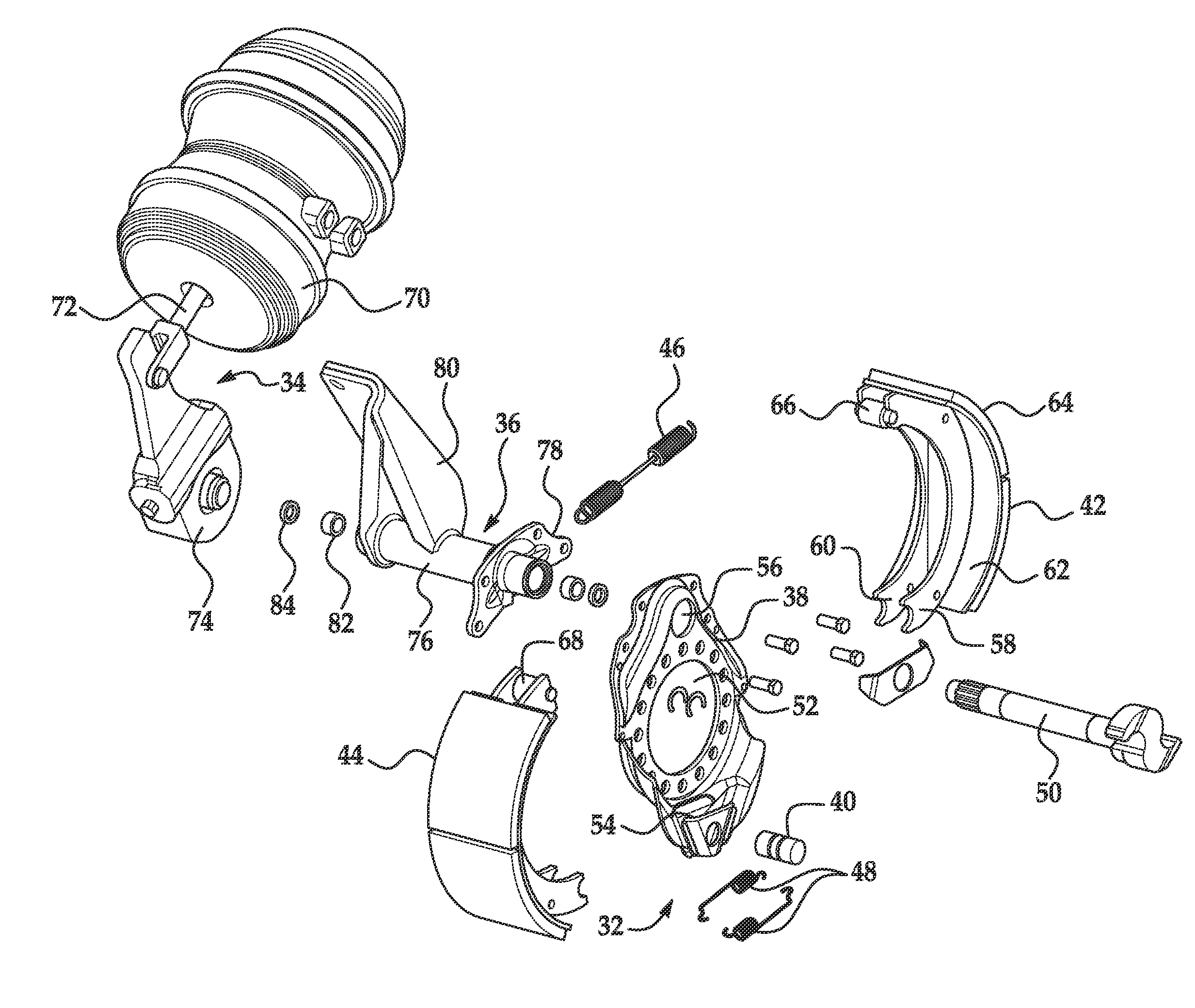
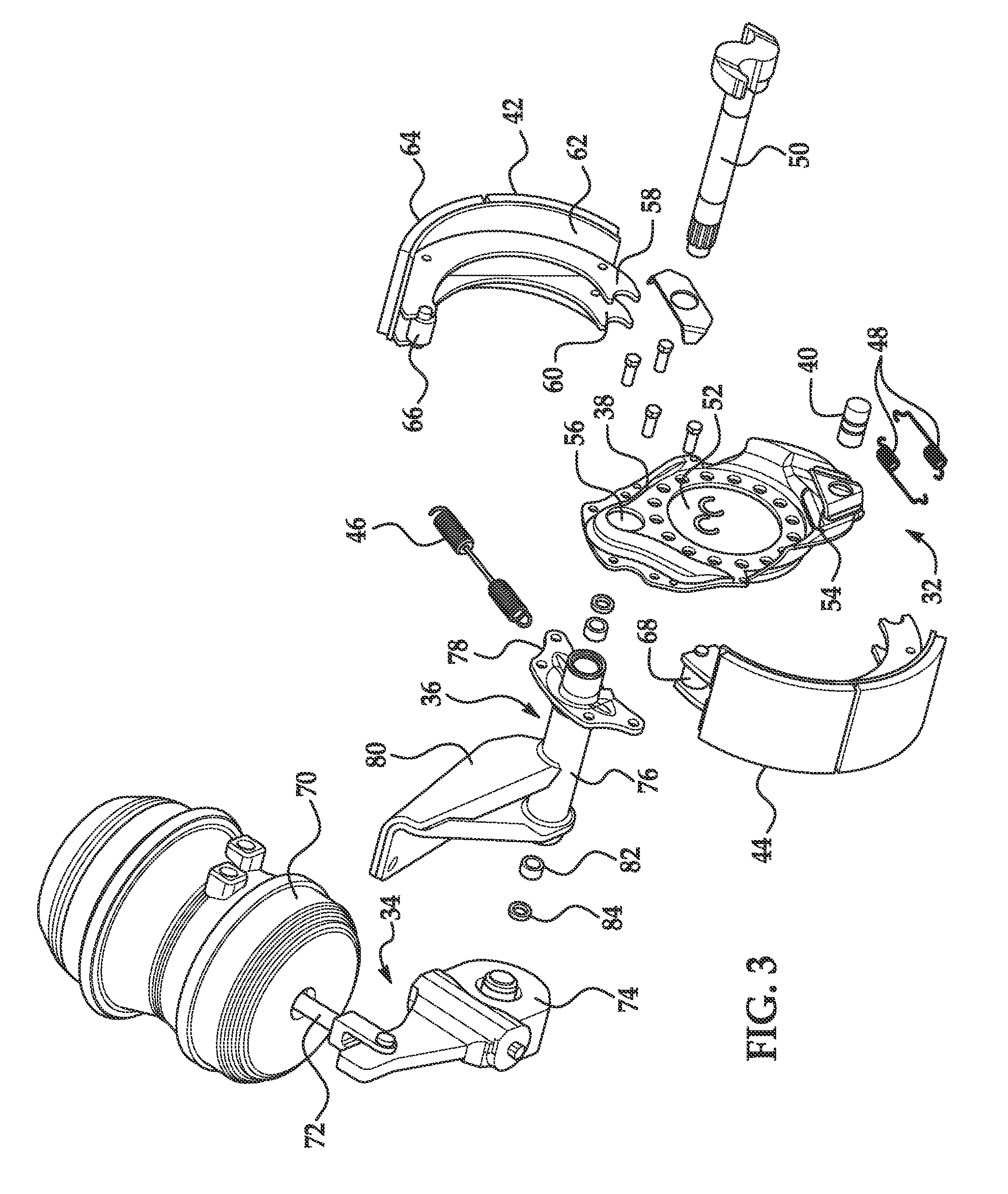
[0021]Referring now to the drawings wherein like reference numerals are used to identify identical components in the various views, FIG. 3 illustrates a brake 32, a brake actuating means 34 and a bracket assembly 36 for mounting the brake 32 and brake actuating means 34 in accordance with one embodiment of the present invention.

[0022]Brake 32 is provided to halt rotation of one or more vehicle wheels. Brake 32 is particularly adapted for use in heavy vehicles. It should be understood, however, that brake 32 may be used on a wide variety of vehicles and in non-vehicular applications. Brake 32 is configured to act against an annular brake drum (not shown) that rotates with the vehicle wheel or wheels at one end of an axle (not shown). Brake 32 may include a brake spider 38, an anchor pin 40, brake shoes 42, 44, return and retaining springs 46, 48, and a camshaft 50.

[0023]Spider 38 is provided to mount the various components of brake 32. Spider 38 defines a central aperture 52 through ...


PUM


Abstract

An improved bracket assembly for receiving a brake assembly and a brake actuator is provided. The bracket assembly includes a tube configured to receive a camshaft of the brake assembly. A brake spider mounting flange is disposed proximate a first end of the tube, defines an aperture configured to allow the tube to extend therethrough, and is configured to receive a brake spider of the brake assembly. An actuator mounting arm is disposed proximate a second end of the tube, is configured for coupling to the brake actuator, and has inboard and outboard members. Each of the inboard and outboard members has a body having a first end affixed to the tube and an actuator mounting flange extending from a second end of the body. The actuator mounting flanges define aligned bores configured to receive a fastener extending from the brake actuator.

Description

BACKGROUND OF THE INVENTION[0001]a. Field of the Invention[0002]This invention relates to vehicle brakes. In particular, the invention relates to a bracket assembly for mounting a brake assembly and a brake actuator that is better able to withstand mechanical stress within the bracket assembly as compared to conventional bracket assemblies yet is easier to manufacture than conventional bracket assemblies.[0003]b. Background Art[0004]In a conventional drum brake, a brake drum rotates with a wheel or wheels proximate to one end of an axle. The drum defines a radially inner braking surface. A brake spider is disposed about the axle and a pair of brake shoes are pivotally mounted at one end to the brake spider. The opposite end of each brake shoe is engaged by an actuating member such as a cam to move the brake shoes between positions of engagement and disengagement with the braking surface of the brake drum. The cam is driven by a brake actuator acting on one end of a camshaft supporti...

Claims


Application Information

Patent Timeline
Patent Type & Authority Applications(United States)
IPC IPC(8): F16D65/00F16D51/28
CPCF16D65/0056F16D2051/003F16D51/28F16D51/22F16D65/60F16D2121/08F16D2125/30
Inventor BERWANGER, FRED W.
Owner BENDIKS SPAJSER FAUNDEJSHN BREJK LLK
Why Eureka
Try Eureka