Modular track wiring assembly for a hydronic system

a technology of hydronic systems and modules, applied in the direction of heating types, space heating and ventilation details, domestic heating details, etc., can solve the problems of post-installation service and service may be very difficul

Active Publication Date: 2017-02-02
B2 PROD LTD
View PDF6 Cites 16 Cited by
  • Summary
  • Abstract
  • Description
  • Claims
  • Application Information

AI Technical Summary

Problems solved by technology

The complexity and non-uniformity of existing control systems may lead to wiring errors and poor electrical connections that can result in the need for post-installation service.
Such servicing may be very difficult because poor installations are often disorganized and troubleshooting thus may be challenging.

Method used


Image

  • Modular track wiring assembly for a hydronic system
  • Modular track wiring assembly for a hydronic system
  • Modular track wiring assembly for a hydronic system

Examples


Embodiment Construction

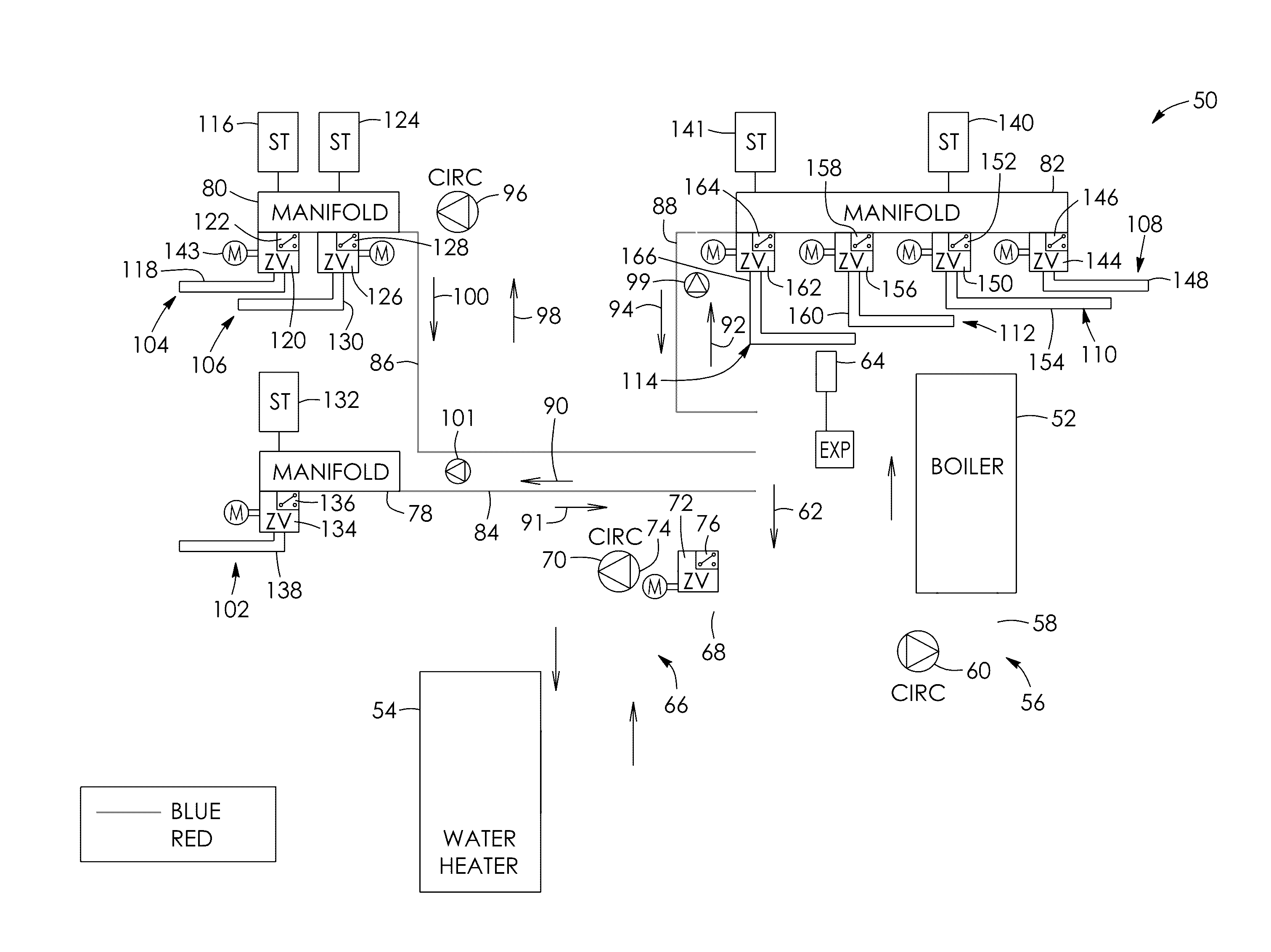
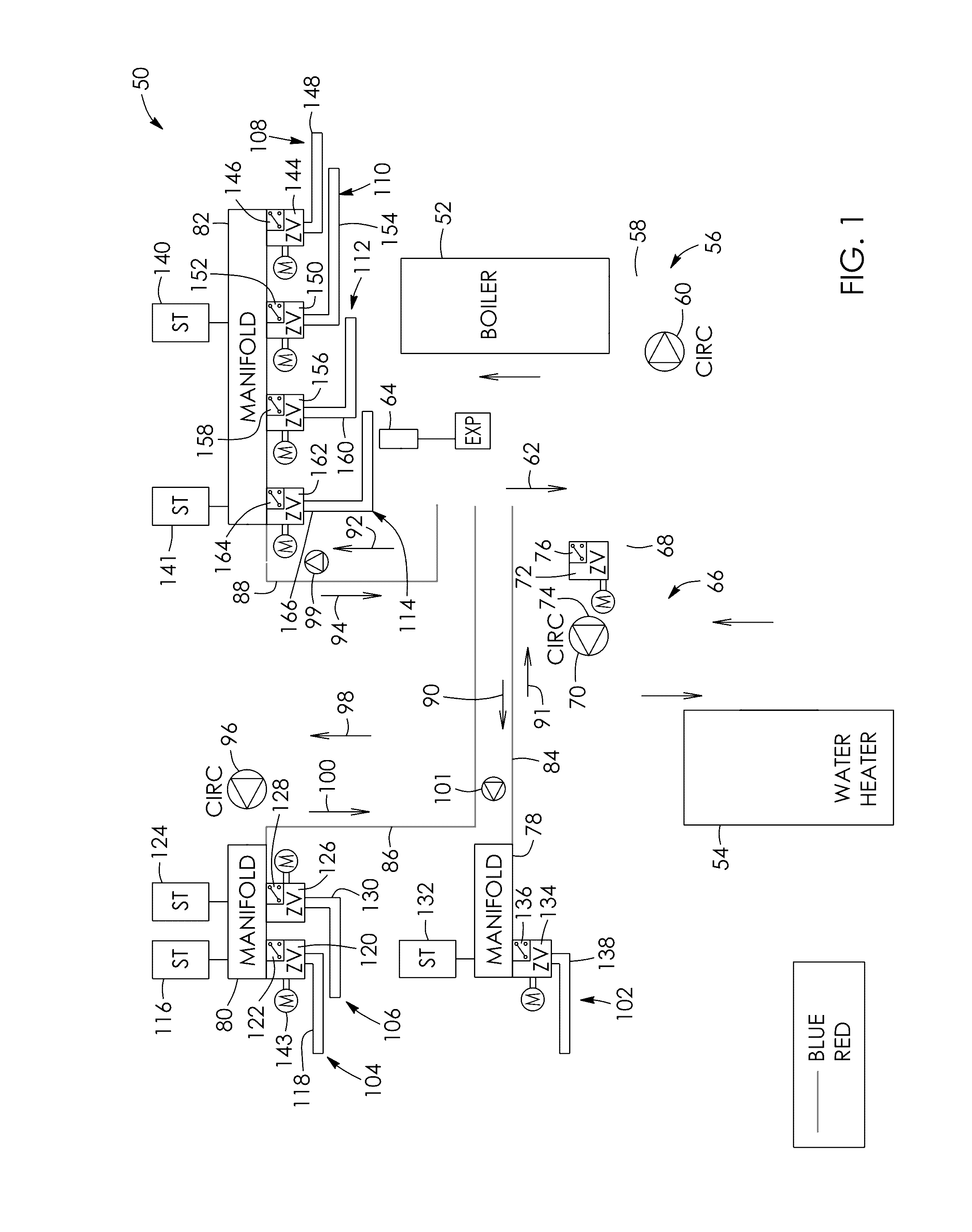
[0042]Referring to the drawings and first to FIG. 1, there is shown a schematic view of a multi-zone hydronic system 50 according to one aspect, with the wiring circuits not being shown.

[0043]Water for domestic use is heated indirectly via a coil inside a fluid heater in the form of a water heater 54 in this example. The system includes a central fluid circuit 56 comprising a central fluid loop, in this example a central water loop 58 through which water may be circulated. The central water loop is in communication with the boiler 52 for selectively heating the fluid therein. The central fluid circuit includes a circulation pump 60 which when activated circulates fluid into and out of the boiler for heating said fluid, as generally shown by arrow of numeral 62. The central fluid circuit 56 includes an air separator 64 configured to remove air from the central water loop 58.

[0044]The hydronic system 50 includes a water heater fluid circuit 66 that includes an auxiliary fluid loop, in...


PUM


Abstract

There is provided a hydronic system for a plurality of zones. The system includes a wiring track. The track has a pair of power conductors for supplying electrical energy therealong and a pair of signal conductors. The signal conductors are in communication with a heat / cold source. The system includes a plurality of zone modules, each corresponding to a respective one of the zones. Each of the zone modules includes leads which connect to respective ones of the conductors. Each of the zone modules includes terminals and conductors configured to selectively connect respective thermostats and zone valves of their zone together, receives signals therefrom and conveys the signals via the signal conductors to the heat / cold source for selectively heating / cooling respective ones of the zones.

Description

BACKGROUND OF THE INVENTION[0001]Field of the Invention[0002]There is provided a modular track wiring assembly. In particular, there is provided a modular track wiring assembly for a hydronic system.[0003]Description of the Related Art[0004]Multi-zone hydronic systems may comprise a number of interrelated components: a source of heat (typically a boiler), circulation pumps to move water around the system, and heat output emitters (radiators, radiant heating panels, fan coil units), zone control valves and thermal or mechanical controls (thermostats, aquastats, switches). A complete system will usually be made up of one or more heat sources, one or more circulation pumps and a number of heat output devices and emitters located at various locations where heat is needed throughout the building.[0005]To maintain desired space temperatures, a plurality of thermostats are often installed. Each thermostat works to turn on and off the flow of hot water through one or more of the heat output...

Claims


Application Information

Patent Timeline
Patent Type & Authority Applications(United States)
IPC IPC(8): F24D19/10F24D3/08F24D3/02
CPCF24D19/1015F24D3/02F24D19/1012F24D19/1048F24D3/08G05D23/1934H01R25/14H01R25/142F24D2220/0207F24D19/1066F24D2220/042F24D2220/0271Y02B30/70F24D19/10
Inventor O'CONNOR, BRENDAN A.BUNT, BRAD
Owner B2 PROD LTD
Why Eureka
Try Eureka