Floorboards provided with a mechanical locking system

a technology of mechanical locking system and floorboard, which is applied in the direction of flooring, covering/lining, construction, etc., can solve the problems of difficulty in locking the floorboard, difficulty in joining the floorboard, and difficulty in locking the mechanical locking system such as the tongue and the tongue groove, so as to facilitate the locking of the floorboard

Active Publication Date: 2017-02-09
VÄLINGE INNOVATION AB
View PDF5 Cites 33 Cited by
  • Summary
  • Abstract
  • Description
  • Claims
  • Application Information

AI Technical Summary

Benefits of technology

[0008]Another object of at least certain embodiment of the present disclosure is to facilitate locking of floorboards by means of a mechanical locking system when the floorboards have different thicknesses.
[0009]A further object of at least certain embodiment of the present disclosure is to facilitate locking of floorboards by means of a mechanical locking system when no underlying foam is used.
[0011]An advantage of embodiments of the present disclosure is that the calibrating groove compensates for floorboards having different thicknesses, especially a difference in thickness at the edges of the floorboards. The calibrating groove allows the second edge to be pushed towards a sub-floor on which the floorboards are arranged. Thereby, the second edge may be displaced such that an upper side of the second floorboard is aligned with an upper side of the first floorboard at the first and second edges, respectively, even if the thickness of the second floorboard exceeds the thickness of the first floorboard.
[0012]Another advantage of embodiments of the present disclosure is that locking of the floorboards may be facilitated. Conventionally, due to different floorboards having different thicknesses, locking of portions of the mechanical locking system such as a tongue and a tongue groove, may be hindered. The tongue may have difficulties in entering into engagement with the tongue groove for locking as discussed above. By providing the calibrating groove of the present disclosure, the second edge may be bent downwards until a locking position in which the tongue enters into the tongue groove is reached.
[0014]At least the second floorboard may be flexible. The flexibility or resiliency of the second edge, or of the floorboard, allows the second edge to be bent downwards towards the sub-floor.

Problems solved by technology

This may result in difficulties when joining the floorboards, since the floorboards may not enter into a locking position.
However, such differences in thickness of the floorboards usually does not results in problems when locking the floorboards together when the floorboards are arranged on a foam provided on the sub-floor.
As a result, the differences in thickness between different floorboards may result in difficulties when locking the floorboards together, especially when joining the floorboards by a so called fold down technique.
As described above, floorboards having different thickness may result in the tongue groove of one floorboard being positioned at a different height than the tongue of the adjacent floorboard, resulting in difficulties when joining the floorboards, because the floorboards may not enter into a locking position.
Conventionally, due to different floorboards having different thicknesses, locking of portions of the mechanical locking system such as a tongue and a tongue groove, may be hindered.

Method used


Image

  • Floorboards provided with a mechanical locking system
  • Floorboards provided with a mechanical locking system
  • Floorboards provided with a mechanical locking system

Examples


Embodiment Construction

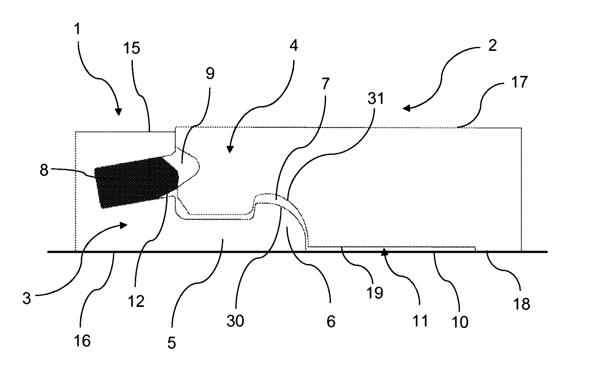
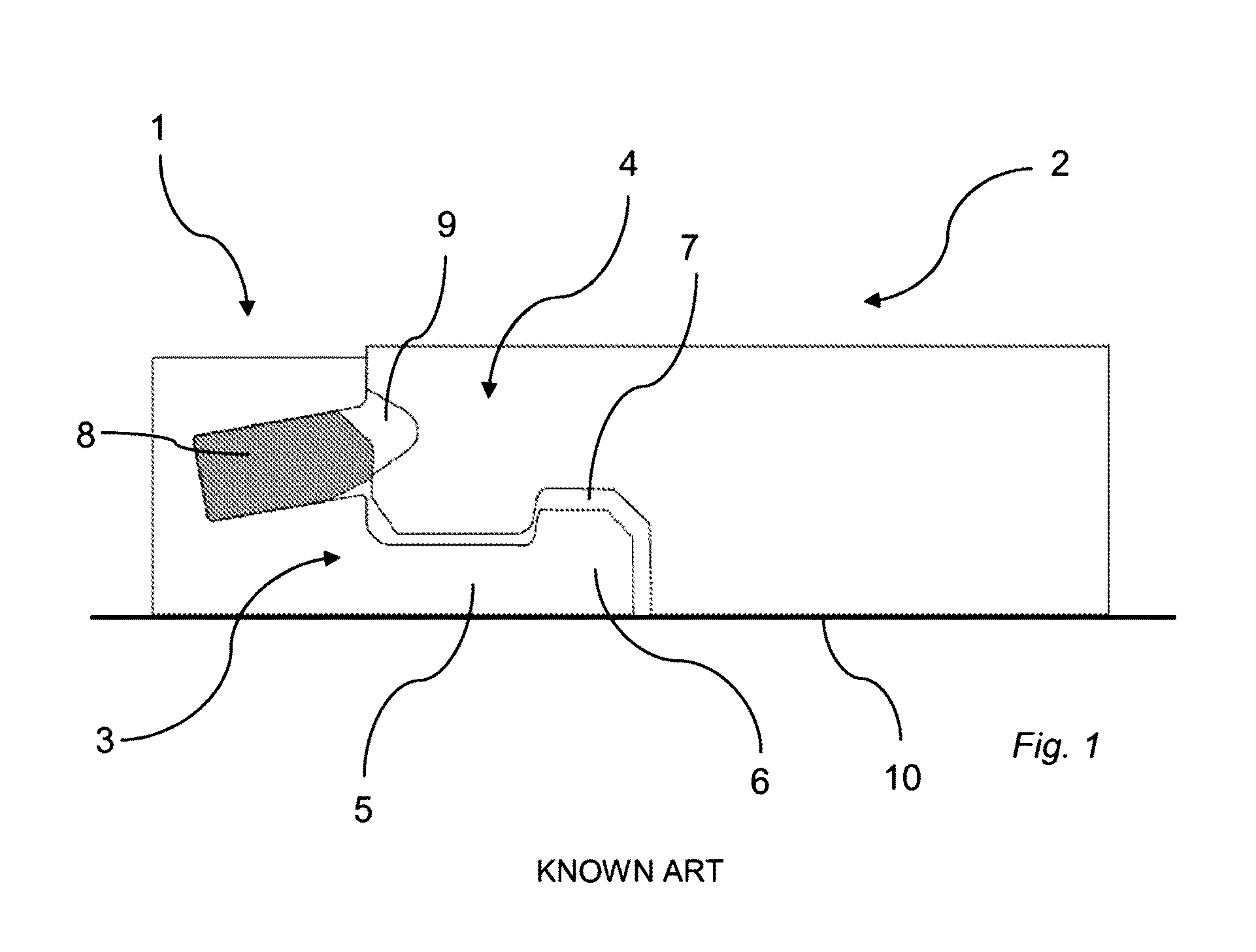
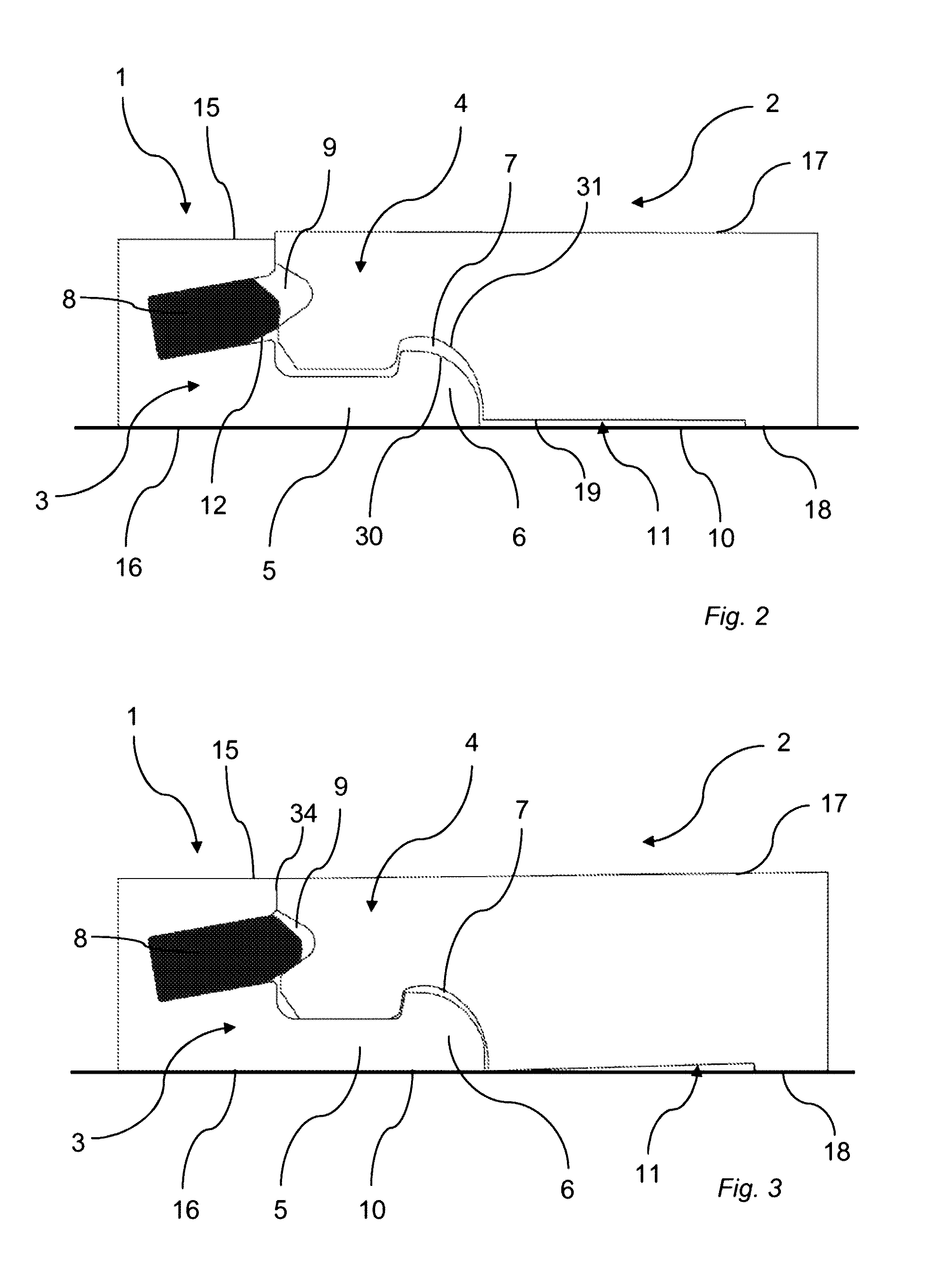
[0048]FIGS. 2, 3, 4 and 5 show a mechanical locking system of a set of floorboards comprising at least a first floorboard 1 and a second floorboard 2. FIGS. 6a and 6b show the first floorboard 1 and the second floorboard 2, respectively. The first and second floorboards 1, 2 are arranged on a sub-floor 10. The first floorboard 1 has an upper side 15 facing away from the sub-floor 10 and a lower side 16 facing toward the sub-floor 10. The second floorboard 2 has an upper side 17 facing away from the sub-floor 10 and a lower side 18 facing toward the sub-floor 10.

[0049]The first and second floorboards 1, 2 are provided with the mechanical locking system. The mechanical locking system comprises a locking strip 5. The locking strip 5 protrudes from a first edge 3 of the first floorboard 1. The locking strip 5 is provided with a locking element 6. The locking element 6 is configured to cooperate with a locking groove 7 arranged at the lower side 18 of a second edge 4 of the second floorb...


PUM


Abstract

Floorboards provided with a mechanical locking system including a locking strip protruding from a first edge of a first floorboard. The locking strip is provided with a locking element configured to cooperate with a locking groove at a lower side of a second edge of a second floorboard for locking the first edge and the second edge in a horizontal direction. The first edge and the second edge are configured to be assembled by a vertical downward motion of the second edge towards the first edge. The second edge is provided with a calibrating groove adjacent the locking groove. Also, a method for producing a mechanical locking system.

Description

CROSS REFERENCE TO RELATED APPLICATIONS[0001]The present application is a continuation of U.S. application Ser. No. 14 / 224,628, which claims the benefit of Swedish Application No. 1350377-6, filed on Mar. 25, 2013. The entire contents of U.S. application Ser. No. 14 / 224,628 and Swedish Application No. 1350377-6 are hereby incorporated herein by reference in their entirety.TECHNICAL FIELD[0002]The present disclosure relates to floorboards provided with a mechanical locking system, and a method for producing a mechanical locking system at edges of floorboards.TECHNICAL BACKGROUND[0003]Due to tolerances allowed during manufacturing, the thickness of different floorboards may slightly differ. As a consequence, different portions of a mechanical locking system may be arranged at different heights of the floorboards. For example, the distance from the sub floor on which the floorboards are arranged to a tongue arranged on a first floorboard may be different from the distance from the sub ...

Claims


Application Information

Patent Timeline
Patent Type & Authority Applications(United States)
IPC IPC(8): E04F15/02
CPCE04F15/02038E04F15/02E04F15/02033E04F2201/0146E04F2201/042E04F2201/0547E04F2203/08E04F15/107
Inventor BOO, CHRISTIAN
Owner VÄLINGE INNOVATION AB
Why Eureka
Try Eureka