Continuous variable valve timing control device and control method therefor

a control device and valve timing technology, applied in the direction of electric control, machine/engine, data switching network, etc., can solve the problems of increasing operation load, reducing engine efficiency, delay of engine mixer, etc., and achieve the effect of reducing operation load

Inactive Publication Date: 2017-02-09
HYUNDAI KEFICO CORP
View PDF5 Cites 5 Cited by
  • Summary
  • Abstract
  • Description
  • Claims
  • Application Information

AI Technical Summary

Benefits of technology

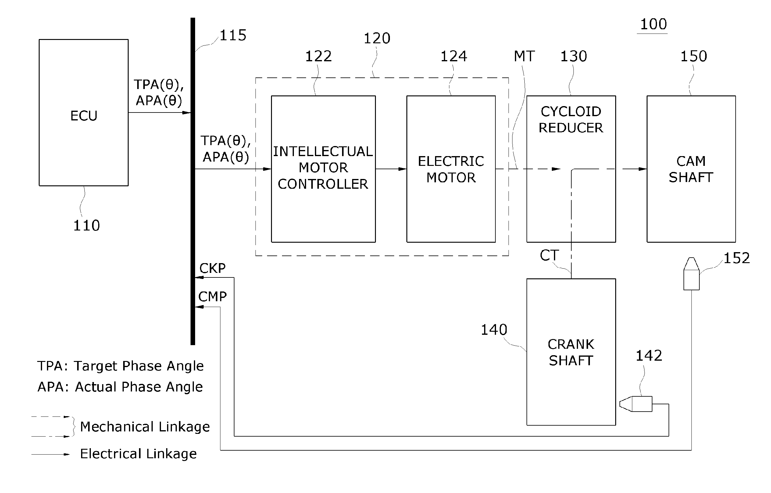
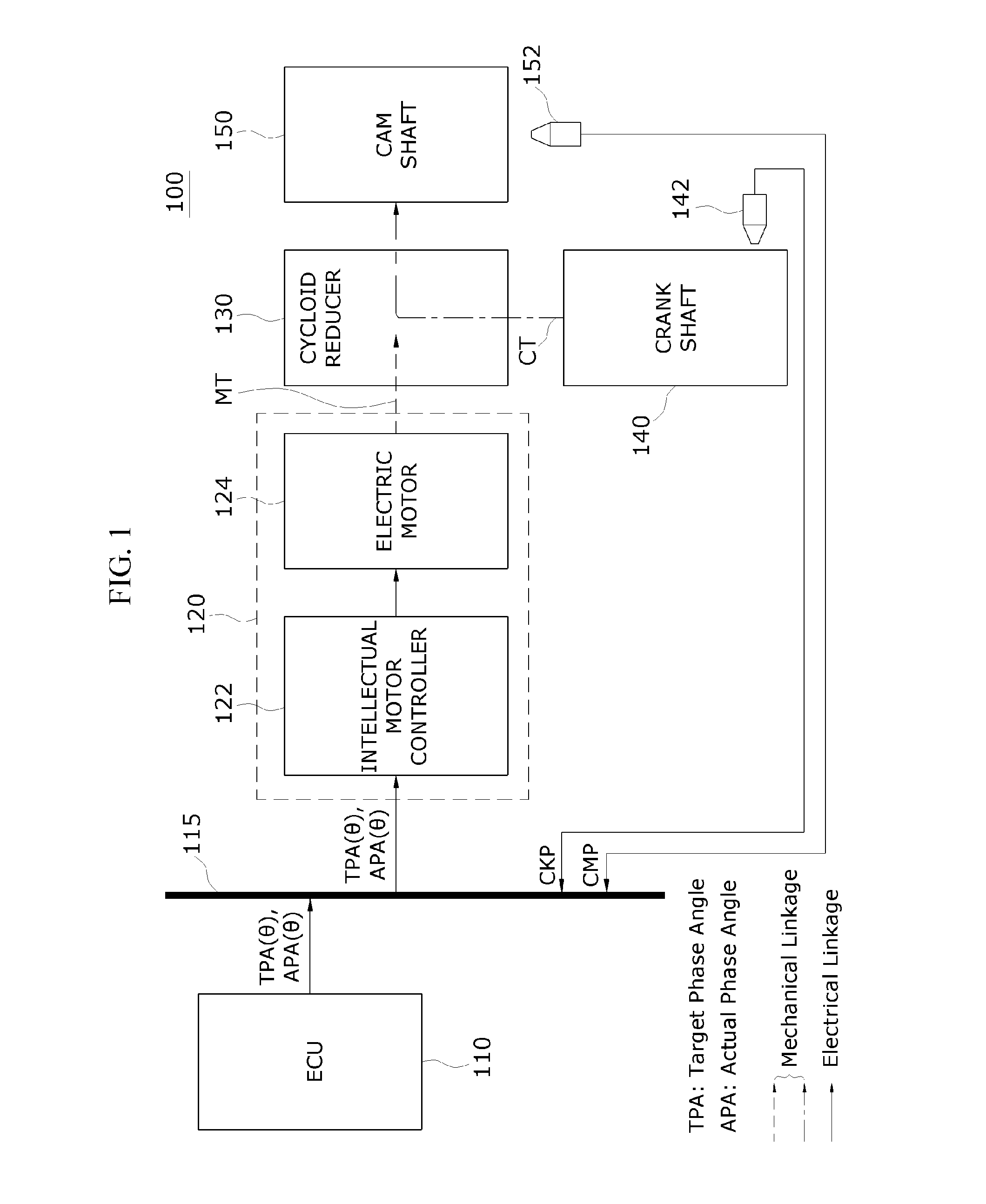
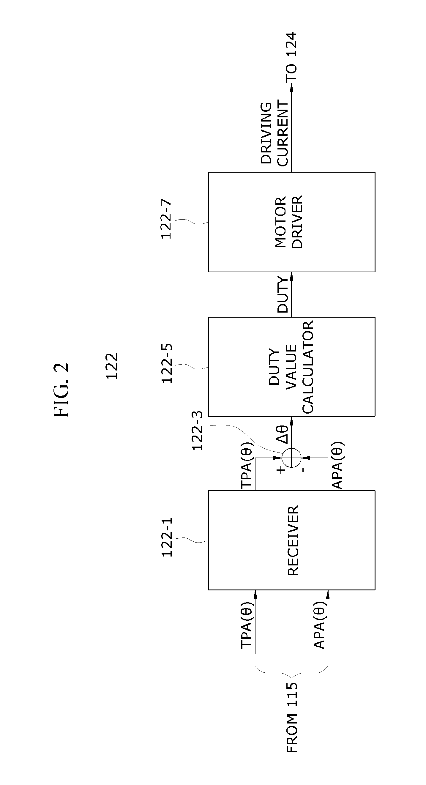
[0010]The present invention provides a CVVT control device and method which decrease an operation load performed by an ECU for controlling a CVVT. In one general aspect, a continuously variable valve timing (CVVT) control device may include an engine controlling unit (ECU) configured to output an actual phase angle and a target phase angle of an intake valve or an exhaust valve and an intellectual motor controller configured to receive the actual phase angle and the target phase angle from the ECU through digital communication in a vehicle. A driving current may be generated to adjust an output torque of a motor based on a phase deviation between the received actual phase angle and target phase angle.
[0011]In another exemplary embodiment, a continuously variable valve timing (CVVT) control device may include an engine controlling unit (ECU) that may be configured to output a target phase angle of an intake valve or an exhaust valve and an intellectual motor controller that may be configured to receive the target phase angle from the ECU through digital communication in a vehicle.

Problems solved by technology

When the valve opening and closing timing is controlled at a high speed, a compression stroke which occurs in the mixer of the engine is delayed and an efficiency of the engine is reduced.
In particular, the ECU that performs a number

Method used


Image

  • Continuous variable valve timing control device and control method therefor
  • Continuous variable valve timing control device and control method therefor
  • Continuous variable valve timing control device and control method therefor

Examples


Embodiment Construction

[0020]Hereinafter, the exemplary embodiment of the present invention will be described in detail with reference to the accompanying drawings to allow those skilled in the art to easily practice the present invention. Advantages and features of the present invention and methods for achieving the same will be clearly understood with reference to the following detailed description of embodiments in conjunction with the accompanying drawings. However, the present invention is not limited to the embodiments disclosed herein, but may be implemented in various different forms. The embodiments are merely given to make the disclosure of the present invention complete and to completely instruct the scope of the invention to those skilled in the art, and the present invention should be defined by the scope of the claims.

[0021]The terminology used herein is for the purpose of describing particular embodiments only and is not intended to be limiting of the invention. As used herein, the singular...


PUM


Abstract

A continuously variable valve timing (CVVT) control device is provided. The CVVT control device includes an engine controlling unit (ECU) configured to output an actual phase angle and a target phase angle of an intake valve or an exhaust valve. The CVVT control device further includes an intellectual motor controller configured to receive the actual phase angle and the target phase angle from the ECU through digital communication in a vehicle. A driving current is generated for adjusting an output torque of a motor based on a phase deviation between the received actual phase angle and target phase angle.

Description

CROSS-REFERENCE TO RELATED APPLICATIONS[0001]This is a continuation application of International Application No. PCT / KR2015 / 004861 filed May 14, 2015, which claims priority to Korean Application No. 10-2014-0058386 filed May 15, 2014. The applications are incorporated herein by reference.BACKGROUND[0002]Field of the Invention[0003]The present invention relates to a continuously variable valve timing (CVVT) control device and method, and more particularly, to a CVVT control device and method using a motor.[0004]Description of the Related Art[0005]Typically, automotive engineering, technology (hereinafter referred to as VVT control technology) that controls a variable valve timing (VVT) describes adjusting an opening and closing timing of a valve based on revolutions of an engine. Since the VVT control technology adjusts a valve opening and closing timing based on a low-speed rotation and a high-speed rotation of an engine enhances the fuel vehicles that include the VVT control techno...

Claims


Application Information

Patent Timeline
IPC IPC(8): F01L1/344F02D41/26F02D13/02
CPCF01L1/344F02D13/0219H04B1/16H04L12/6418H04L12/46F02D41/26F01L1/34F02D41/009F02D41/266F01L1/352H04L12/413F02D2041/001Y02T10/12F02D13/02F01L2201/00F01L2013/103F01L2820/032F01L2013/113F01L2820/042F01L2800/14F01L2013/111F01L2820/041
Inventor BAEK, JIN WOOKKIM, NAM KYULEE, JONG RIMCHO, KYOUNG HO
Owner HYUNDAI KEFICO CORP
Why Eureka
Try Eureka