Wireless power system with a self-regulating wireless power receiver

a wireless power receiver and wireless power technology, applied in circuit authentication, battery data exchange, transmission, etc., can solve the problems of receivers taking considerable time, fcc part 15 subpart c compliance testing becomes difficult, and it is not desirable to have a wide range of wireless power transfer frequency of operation, etc., to achieve effective and faster over voltage protection, quick remedial action, and fast response time

Active Publication Date: 2017-02-09
WIPQTUS
View PDF2 Cites 22 Cited by
  • Summary
  • Abstract
  • Description
  • Claims
  • Application Information

AI Technical Summary

Benefits of technology

[0008]The wireless power receiver, via the auto-tuning network, self-regulates to draw the required amount of power from a wireless power transmitter. In a sudden over voltage condition, for example, on account of a load transient, the auto-tuning network detects the over voltage and performs quick remedial action. The auto-tuning network provides effective and faster over voltage protection (OVP) than possible with a scheme that relies on communicating with the wireless power transmitter. The need for a conventional communication protocol from the wireless power receiver to the wireless power transmitter is obviated since the functions that require the communication protocol to exist are handled by the auto-tuning network with significantly faster response times.
[0009]The method and system disclosed herein also simplifies the wireless power transmitter design. The wireless power transmitter does not need a conventional modulator/demodulator block and an out-of-band communication block typically contained in the wireless power transmitter for processing messages from and communicating messages to the wireless power receiver. The wireless power receiver, via the auto-tuning network, receives the required amount of wirelessly transmitted power from the wireless power transmitter without communicating messages to the wireless power transmitter. As a result, a few of the wireless protocol communication function blocks, such as the modulator/demodulator block and the out-of-band communication block that are typically contained in the wireless power transmitter can be eliminated. The modulator/demodulator block and the out-of-band communication block are built with many passive components, active components, switches and firmware resources. Therefore, elimination of the modulator/demodulator block and the out-of-band communication block simplifies and ...

Problems solved by technology

However, for some applications, it is not desirable to have a wide range of frequency of operation for wireless power transfer.
Also, Federal Communications Commission (FCC) Part 15 Subpart C compliance testing becomes difficult because of varying frequency and the corresponding harmonics.
The receiver takes considerable amount of time to send the message and the transmitter takes considerable amount of time to decipher the message and react to the sent message, therefore latency is inherent and there is a time delay.
Also, the transmitter may decipher the message incorrectly, the message may be corrupted, etc., which could considerably delay the receiver in exiting from an over voltage condition.
The additional protection circuitry is r...

Method used


Image

  • Wireless power system with a self-regulating wireless power receiver
  • Wireless power system with a self-regulating wireless power receiver
  • Wireless power system with a self-regulating wireless power receiver

Examples


first embodiment

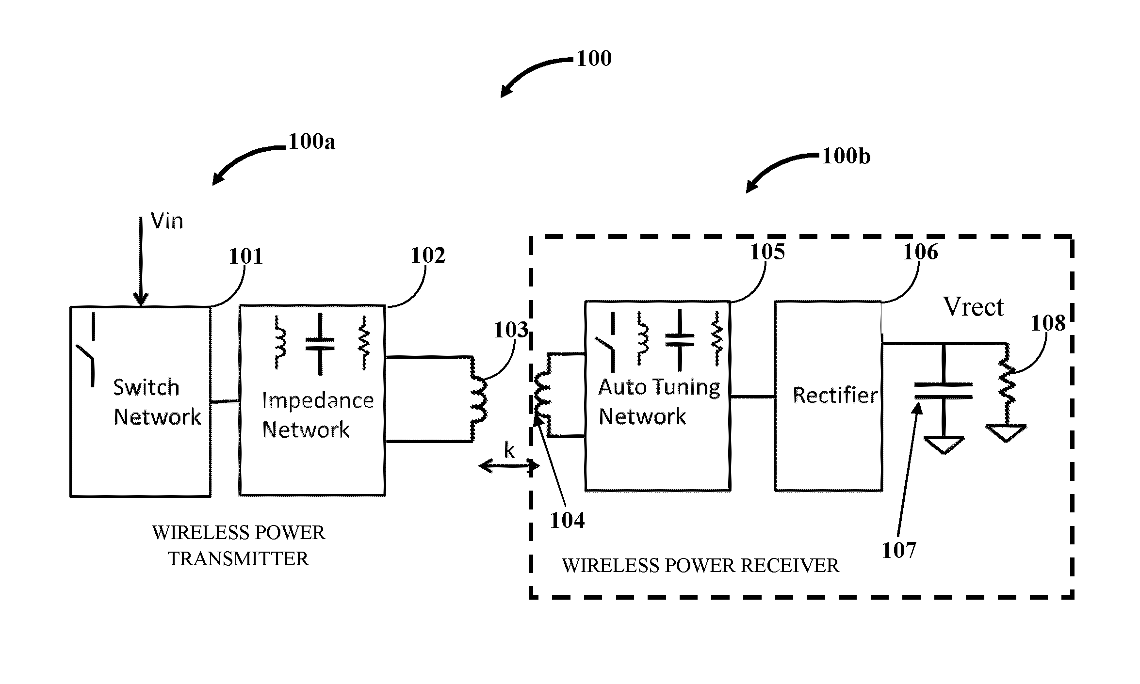
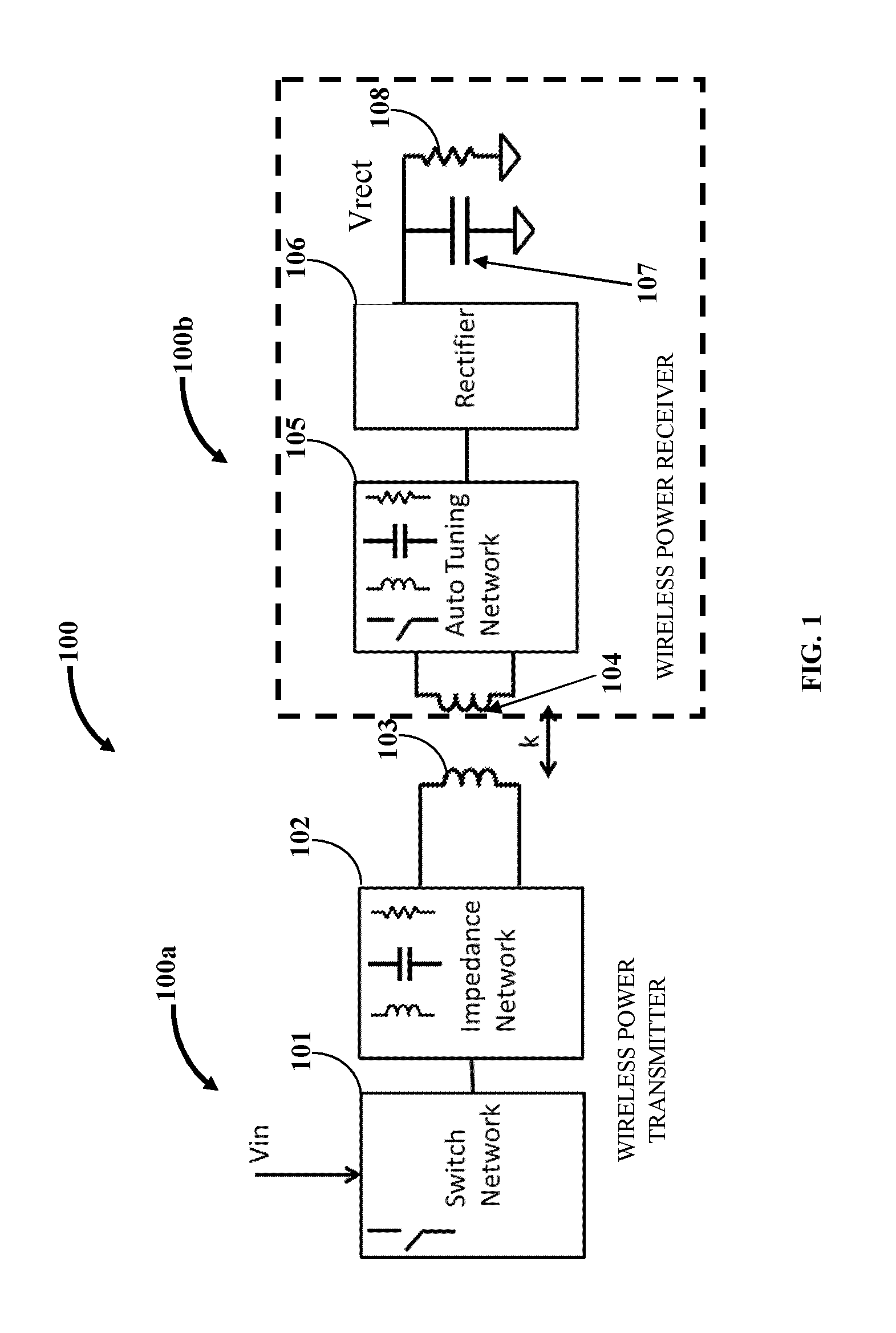
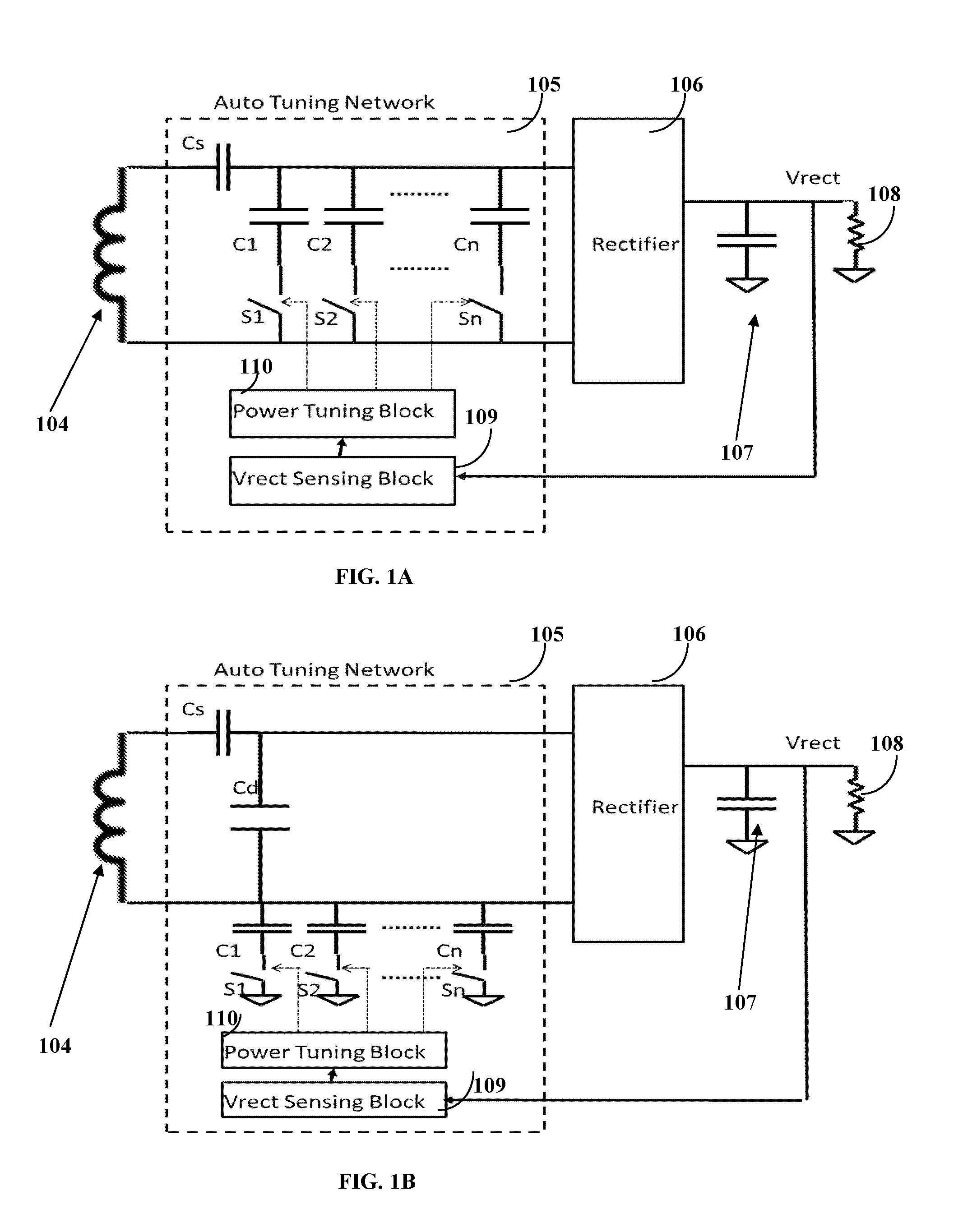
[0026]FIG. 1A exemplarily illustrates the auto-tuning network 105 of the self-regulating wireless power receiver 100b. In this embodiment, the auto-tuning network 105 includes a Vrect Sensing Block 109, a Power Tuning Block 110, a series resonant capacitor Cs and a parallel switch-capacitor network consisting of “n” parallel capacitors C1, C2, . . . Cn and “n” switches S1, S2, . . . Sn. In this embodiment, the parallel switch-capacitor network is connected across the 2 alternating current (AC) IOs of the rectifier 106. The Vrect Sensing Block 109 measures the rectifier 106 output voltage Vrect constantly or periodically. The Power Tuning Block 110 compares the measured voltage Vrect with its configured threshold levels. Based on the comparison, the Power Tuning Block 110 activates switches S1, S2, . . . Sn. The switches may be turned on or turned off or may be pulsed on and off at a certain frequency and duty cycle. When a switch S1, S2, . . . Sn is turned on, the associated capacit...

second embodiment

[0027]FIG. 1B exemplarily illustrates the auto-tuning network 105 of the self-regulating wireless power receiver 100b. In this embodiment, the auto-tuning network 105 includes a Vrect Sensing Block 109, a Power Tuning Block 110, a series resonant capacitor Cs, a parallel resonant capacitor Cd and a parallel switch-capacitor network consisting of “n” parallel capacitors C1, C2, . . . Cn and “n” switches S1, S2, . . . Sn. In this embodiment, the parallel switch-capacitor network is connected asymmetrically between one of the alternating current (AC) IOs of the rectifier 106 and ground. The Vrect Sensing Block 109 measures the rectifier 106 output voltage Vrect constantly or periodically. The Power Tuning Block 110 compares the measured voltage Vrect with its configured threshold levels. Based on the comparison, the Power Tuning Block 110 activates switches S1, S2, . . . Sn. The switches may be turned on or turned off or may be pulsed on and off at a certain frequency and duty cycle. W...

third embodiment

[0028]FIG. 1C exemplarily illustrates the auto-tuning network 105 of the self-regulating wireless power receiver 100b. In this embodiment, the auto-tuning network 105 includes a Vrect Sensing Block 109, a Power Tuning Block 110, a series resonant capacitor Cs, a parallel resonant capacitor Cd, a first parallel switch-capacitor network consisting of “n” parallel capacitors C1, C2, . . . Cn and “n” switches S1, S2, . . . Sn and a second parallel switch-capacitor network consisting of “n” parallel capacitors D1, D2, . . . Dn and “n” switches E1, E2, . . . En. In this embodiment, the two parallel switch-capacitor networks in combination together are connected symmetrically between both the alternating current (AC) IOs of the rectifier 106 and ground. The Vrect Sensing Block 109 measures the rectifier 106 output voltage Vrect constantly or periodically. The Power Tuning Block 110 compares the measured voltage Vrect with its configured threshold levels. Based on the comparison, the Power ...


PUM


Abstract

A method and system for self-regulating wireless power transmitted to a wireless power receiver (WPR) is provided. An auto-tuning network is operably coupled within the WPR. The auto-tuning network comprises an impedance network that dynamically increases, decreases, or maintains amount of the received wirelessly transmitted power by detecting changes in a rectifier load disposed in the WPR and/or in an output voltage of the rectifier in the WPR. The auto-tuning network self-regulates the wireless power received from a wireless power transmitter (WPT) obviating the need for conventional communication messages. The WPT is hence free from a modulator/demodulator block and an out-of-band communication block and can operate over a limited operating range to enable simpler design for passing EMC regulation. Additionally, the WPR implements a receiver-maximum power-signature algorithm for enabling the WPT to detect unsupported receivers, configure its operating point and range, and terminate power transmission when not needed by WPR.

Description

CROSS REFERENCE TO RELATED APPLICATIONS[0001]This application is a continuation-in-part of application Ser. No. 14 / 094,750 filed in the United States Patent and Trademark Office on Dec. 2, 2013 which claims benefit from U.S. Provisional Application No. 61 / 732,412 filed on Dec. 3, 2012.BACKGROUND[0002]In wireless power systems, a receiver and a transmitter communicate with one another using a communication protocol. In a conventional communication protocol, the receiver requests the transmitter to increase, decrease, maintain, stop, etc., the power provided to the receiver. The communication protocol can be “in band” via for example, a load modulation technique, or be “out of band” such as via Bluetooth® of Bluetooth SIG, Inc., Wi-Fi® of the Wireless Ethernet Compatibility Alliance, etc.[0003]Conventional communication protocol based power transfer control involves the transmitter changing its frequency across a few hundred kilo hertz (kHz). However, for some applications, it is not ...

Claims


Application Information

Patent Timeline
IPC IPC(8): H02J50/12H02J50/60
CPCH02J50/60H02J50/12H04B5/0031H04B5/0037H04B5/0081H02J7/00045
Inventor SANKAR, GANAPATHY
Owner WIPQTUS
Why Eureka
Try Eureka