Retinoscope

Active Publication Date: 2017-02-16
HAN JEONG WOO
View PDF2 Cites 0 Cited by
  • Summary
  • Abstract
  • Description
  • Claims
  • Application Information

AI Technical Summary

Benefits of technology

[0028]According to one embodiment of the present invention, a retinoscope can maintain a predetermined distance between an eye of an examinee and a retinoscopy lens and can further maintain a predetermined distance for an optometric examination between the examinee and a retinoscope part. There is also an effect of minimizing spherical aberration as the examination is performed as near the line of sight of the examinee as possible, thereby allowing deriving an objective and accurate examination value.
[0029]Further, a high-definition camera is mounted on a rear side of an aperture of the retinoscope part to scan incident light beams projected into the an eye of the examinee and reflected light beams reflected from a pupil, and a scanned image is displayed so that an examiner diagnoses and correct

Problems solved by technology

Here, the streak retinoscope is widely used since the spot retinoscope has difficulties in examining astigmatism and axis.
However, if dislocation of the line of sight of the examiner and the line of sight of the examinee is large, an error occurs as a measurement is taken away from the center of a cornea.
Hence, there has been a problem in that the larger the error, the harder it is to perform an accurate examination.
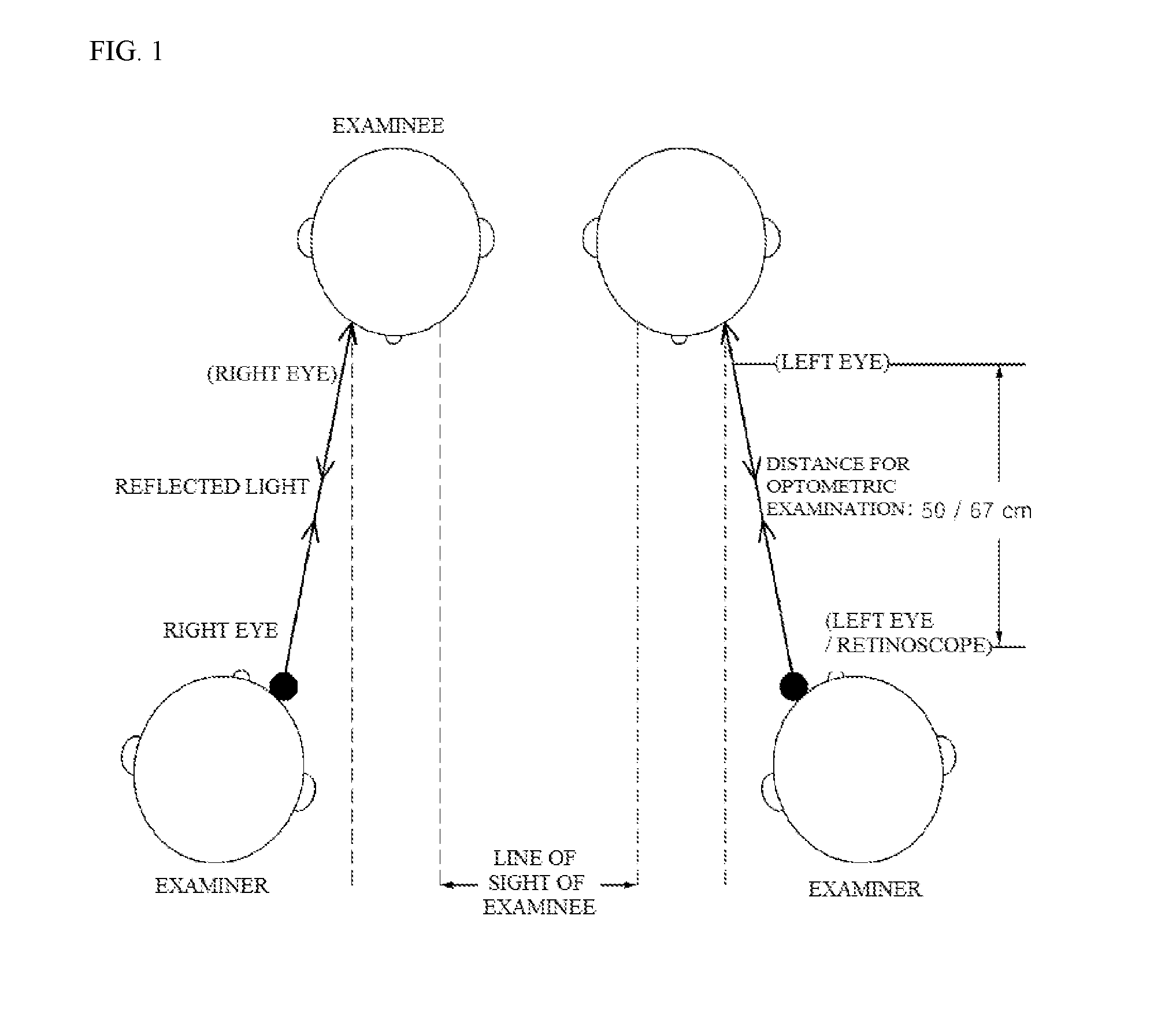
Further, since the examiner has to observe reflected light beams reflected from a small pupil of the examinee at a distance for an optometric examination in a range of 50 cm to 67 cm, it is not easy to observe the reflected light beams.
In particular, if the examinee has a small pupil, it is harder to observe the reflected light beams, thereby increasing eye strain of the examiner.
Further, when the examiner is old or has poor vision, an accurate examination is difficult to be performed.
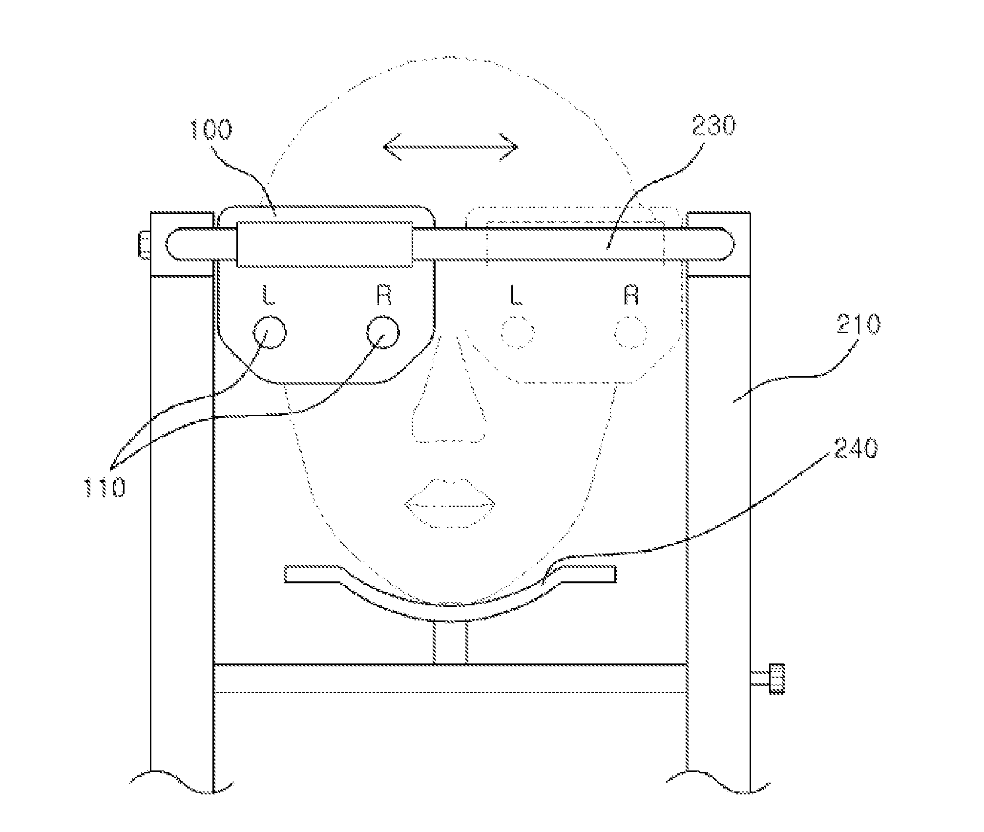
Further, since the examiner has to use his or her right hand and right eye when examining right eye of the examinee and has to use his or her left hand and left eye when examining left eye of the examinee, the examiner feels uncomfortable with examination posture when examining the other side, depending whether the examiner is a right-hander or a left-hander.
There has also been a problem in that the examiner with a tremoring hand cannot perform a refraction examination.
Further, there has been a problem in t

Method used


Image

  • Retinoscope
  • Retinoscope
  • Retinoscope

Examples


Example

MODES OF THE INVENTION

[0038]The above objectives, features, and other advantages of the present invention will become more apparent by describing in detail exemplary embodiments thereof in connection with the accompanying drawings. Hereinafter, exemplary embodiments of a retinoscope of the present invention will be described in detail with reference to the accompanying drawings. For this description, like reference numerals are used for like components unless otherwise described.

[0039]FIG. 2 is a perspective view illustrating a retinoscope according to one embodiment of the present invention, FIG. 3 is a front view illustrating a state in which a refracting unit of the retinoscope according to one embodiment of the present invention is moved laterally, and FIG. 4 is a plan view for describing a rotating member of a retinoscope part in the retinoscope according to one embodiment of the present invention. Further, FIG. 5 is a cross-sectional view schematically illustrating the retinos...


PUM


Abstract

A retinoscope comprises a refracting unit that has a lens module therein and is located at a predetermined distance from eyes of a person to be tested such that a line of sight of the person to be tested passes through an optometry window; a main body for supporting the refracting unit; a retinoscope unit coupled to one surface of the main body and maintained at a predetermined distance from the refracting unit; and the operating unit that operates driving of the refracting unit and the retinoscope unit.

Description

TECHNICAL FIELD[0001]The present invention relates to a retinoscope, and more particularly, to a retinoscope capable of deriving an objective and accurate examination value and improving convenience of an examination.BACKGROUND ART[0002]In general, retinoscopy is an examination method in which certain light beams in front of an examinee are projected into an eye and a pupil of an examinee so that an examiner observes a refractive state of reflected light beams which are reflected from the pupil to find a far point location of the eye of the examinee.[0003]A tool used for the retinoscopy is a retinoscope, and types of retinoscope include a spot retinoscope and a streak retinoscope. Here, the streak retinoscope is widely used since the spot retinoscope has difficulties in examining astigmatism and axis.[0004]As shown in FIG. 1, in a refraction examination using a conventional retinoscope, a distance for an optometric examination between an examinee and an examiner is fixed in a range ...

Claims


Application Information

Patent Timeline
IPC IPC(8): A61B3/103A61B3/00A61B3/14
CPCA61B3/103A61B3/14A61B3/0083A61B3/0075A61B3/0041A61B3/0008A61B3/12A61B3/132A61B3/152A61B3/154A61B3/1035
Inventor HAN, JEONG-WOO
Owner HAN JEONG WOO
Why Eureka
Try Eureka