Apparatus for retinoscopy

a technology of retinoscopy and apparatus, which is applied in the field of retinoscopy, can solve the problems of difficult observation of reflected light beams, difficult to perform accurate examinations, and errors, and achieve the effects of minimizing spherical aberration, improving convenience of examination, and accurately identifying

Inactive Publication Date: 2019-06-11
HAN JEONG WOO
View PDF11 Cites 0 Cited by
  • Summary
  • Abstract
  • Description
  • Claims
  • Application Information

AI Technical Summary

Benefits of technology

[0029]According to one embodiment of the present invention, a retinoscope can maintain a predetermined distance between an eye of an examinee and a retinoscopy lens and can further maintain a predetermined distance for an optometric examination between the examinee and a retinoscope part. There is also an effect of minimizing spherical aberration as the examination is performed as near the line of sight of the examinee as possible, thereby allowing deriving an objective and accurate examination value.
[0030]Further, a high-definition camera is mounted on a rear side of an aperture of the retinoscope part to scan incident light beams projected into the an eye of the examinee and reflected light beams reflected from a pupil, and a scanned image is displayed so that an examiner diagnoses and corrects refractive errors of the eye of the examinee through the displayed image, thereby improving convenience of an examination.
[0031]Further, in comparison to the fact that an angle of astigmatism axis could not been accurately identified because a conventional examiner had to hold a retinoscope part by hand for the examination, the retinoscope part in a fixed state allows checking an inclined angle of light beam axis, thereby accurately identifying an astigmatism axis, leading to an effect that a correction value is accurately derived accordingly.
[0032]Further, an accurate value can be obtained by performing an objective examination, which is distinguished from the examination that has been done in a subjective manner and which could only be performed by a skilled person with a long-term training.

Problems solved by technology

Here, the streak retinoscope is widely used since the spot retinoscope has difficulties in examining astigmatism and axis.
However, if dislocation of the line of sight of the examiner and the line of sight of the examinee is large, an error occurs as a measurement is taken away from the center of a cornea.
Hence, there has been a problem in that the larger the error, the harder it is to perform an accurate examination.
Further, since the examiner has to observe reflected light beams reflected from a small pupil of the examinee at a distance for an optometric examination in a range of 50 cm to 67 cm, it is not easy to observe the reflected light beams.
In particular, if the examinee has a small pupil, it is harder to observe the reflected light beams, thereby increasing eye strain of the examiner.
Further, when the examiner is old or has poor vision, an accurate examination is difficult to be performed.
Further, since the examiner has to use his or her right hand and right eye when examining right eye of the examinee and has to use his or her left hand and left eye when examining left eye of the examinee, the examiner feels uncomfortable with examination posture when examining the other side, depending whether the examiner is a right-hander or a left-hander.
There has also been a problem in that the examiner with a tremoring hand cannot perform a refraction examination.
Further, there has been a problem in that it is hard to maintain a predetermined distance for an optometric examination with the examinee.
While applying diopter with a distance for an optometric examination of 50 cm, if an actual distance for an optometric examination is 50 cm or more or 50 cm or less, an error of 0.25 D unit may occur since a displacement unit of the lens is 0.25 D. Such an error reduces accuracy of the examination, and therefore, it is important to maintain the predetermined distance for an optometric examination.
Further, there is a problem in that it is hard to maintain a predetermined distance between the eye of the examinee and a rack lens located in front of the eye.
While such a manual refraction examination has a great effect of suppressing the intervention of control of the examinee and serves as a useful examination method when communication between the examiner and the examinee is not smooth, location adjustment and an examining posture are very difficult, and considerable effort and time are required to be skillful with the examination method.
In addition, since the examination is performed manually, an error occurs easily, and further, an accurate examination value cannot be obtained since the examination is done in a subjective manner that can only be performed by a skilled person.
Further, it is inconvenient that the examination has to be performed with the rack lens changing in the course of the examination.

Method used


Image

  • Apparatus for retinoscopy
  • Apparatus for retinoscopy
  • Apparatus for retinoscopy

Examples


Embodiment Construction

[0039]The above objectives, features, and other advantages of the present invention will become more apparent by describing in detail exemplary embodiments thereof in connection with the accompanying drawings. Hereinafter, exemplary embodiments of a retinoscope of the present invention will be described in detail with reference to the accompanying drawings. For this description, like reference numerals are used for like components unless otherwise described.

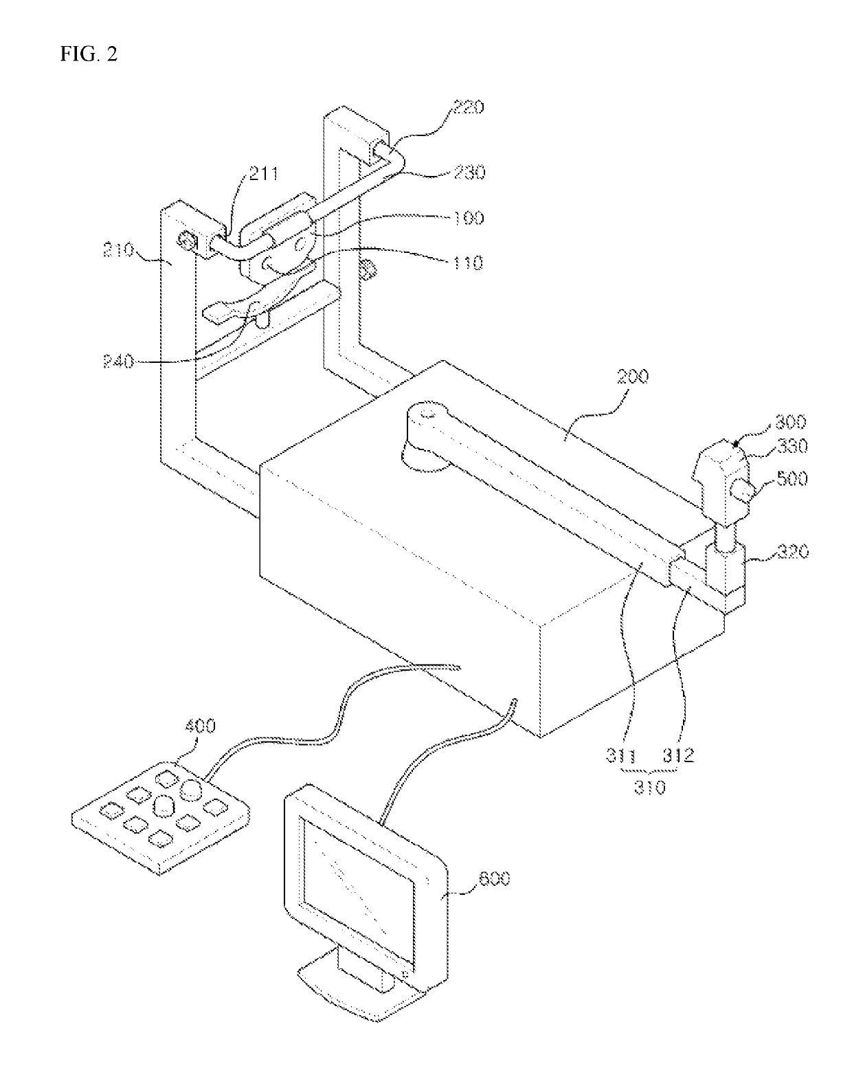
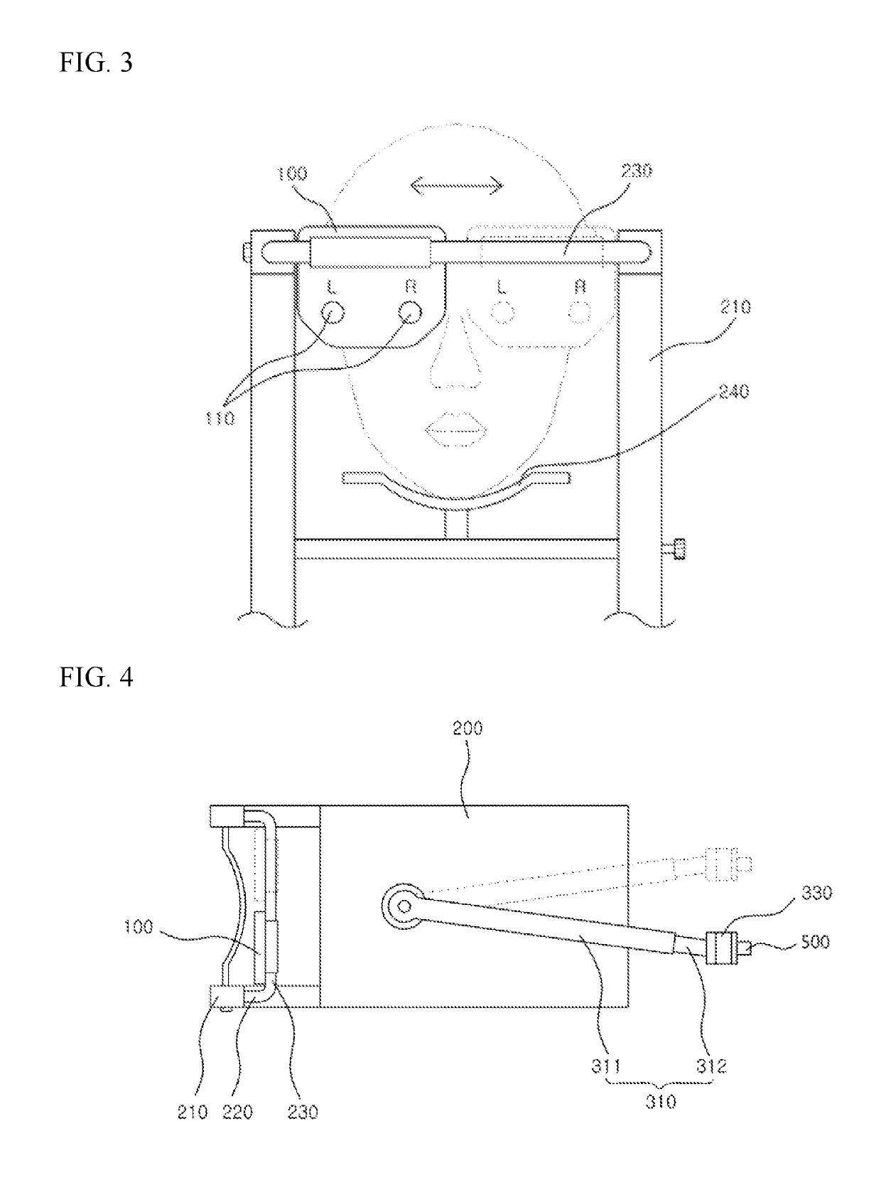
[0040]FIG. 2 is a perspective view illustrating a retinoscope according to one embodiment of the present invention, FIG. 3 is a front view illustrating a state in which a refractor of the retinoscope according to one embodiment of the present invention is moved laterally, and FIG. 4 is a plan view for describing a rotating member of a retinoscope part in the retinoscope according to one embodiment of the present invention. Further, FIG. 5 is a cross-sectional view schematically illustrating the retinoscope part in the retinoscope...


PUM


Abstract

The present invention provides a retinoscope comprising: a refractor that has a lens module therein and is located at a predetermined distance from eyes of a person to be tested such that a line of sight of the person to be tested passes through an optometry window, wherein the lens module is configured such that a plurality of lenses necessary for correction are selectively located on the optometry window in order to obtain a correction value for correcting the eyes of the person to be tested; a main body for supporting the refractor; a retinoscope unit coupled to one surface of the main body and maintained at a predetermined distance from the refractor, wherein the retinoscope unit radiates light beams to the eyes of the person to be tested so as to be close to the line of sight of the person to be tested and rotates or reciprocates the light beams when receiving a signal of an operating unit; and the operating unit that operates driving of the refractor and the retinoscope unit.

Description

CROSS REFERENCE TO PRIOR APPLICATIONS[0001]This application is a National Stage Application of PCT International Patent Application No. PCT / KR2015 / 003650 filed on Apr. 13, 2015, under 35 U.S.C. § 371, which claims priority to Korean Patent Application No. 10-2014-0049820 filed on Apr. 25, 2014, which are all hereby incorporated by reference in their entirety.TECHNICAL FIELD[0002]The present invention relates to a retinoscope, and more particularly, to a retinoscope capable of deriving an objective and accurate examination value and improving convenience of an examination.BACKGROUND ART[0003]In general, retinoscopy is an examination method in which certain light beams in front of an examinee are projected into an eye and a pupil of an examinee so that an examiner observes a refractive state of reflected light beams which are reflected from the pupil to find a far point location of the eye of the examinee.[0004]A tool used for the retinoscopy is a retinoscope, and types of retinoscope...

Claims


Application Information

Patent Timeline
Patent Type & Authority Patents(United States)
IPC IPC(8): A61B3/14A61B3/103A61B3/00
CPCA61B3/103A61B3/0041A61B3/14A61B3/0083A61B3/0075A61B3/0008A61B3/12A61B3/132A61B3/152A61B3/154A61B3/1035
Inventor HAN, JEONG-WOO
Owner HAN JEONG WOO
Why Eureka
Try Eureka