Optical disc

a technology of optical discs and optical discs, applied in the field of optical discs, can solve the problems of not being selected and used, not being practicable, and difficult to change the refractive index of the light-transmitting layer, and achieve the effect of reducing spherical aberration

Inactive Publication Date: 2006-01-12
SONY CORP
View PDF1 Cites 0 Cited by
  • Summary
  • Abstract
  • Description
  • Claims
  • Application Information

AI Technical Summary

Benefits of technology

[0011] An object of this invention is to provide an optical disc that has light-transmitting layer whose refractive index can easily be adjusted to the design refractive index of the objective lens, thereby to reduce spherical aberration greatly.
[0013] In the optical disc of this invention, thus configured, the light-transmitting layer is composed of at least two material layers having different refractive indices. The refractive index of the light-transmitting layer as a whole is determined by the refractive indices of the materials of the material layers. The refractive index of the light-transmitting layer can therefore be made to approach the refractive index that objective lens should have (i.e., the design refractive index of the objective lens), by using desirable materials for the material layers or by adjusting the material layers in thickness. This renders it possible to minimize the spherical aberration.

Problems solved by technology

It is extremely difficult, however, to change the refractive index of the light-transmitting layer, because the refractive index is specific to the material of the light-transmitting layer.
This is not so practical a method.
Should there exist such a material, it could not be selected and used due to its other physical properties such as mechanical strength.

Method used


Image

  • Optical disc
  • Optical disc
  • Optical disc

Examples


Embodiment Construction

[0021] An optical disc according to the present invention will be described, with reference to the accompanying drawings.

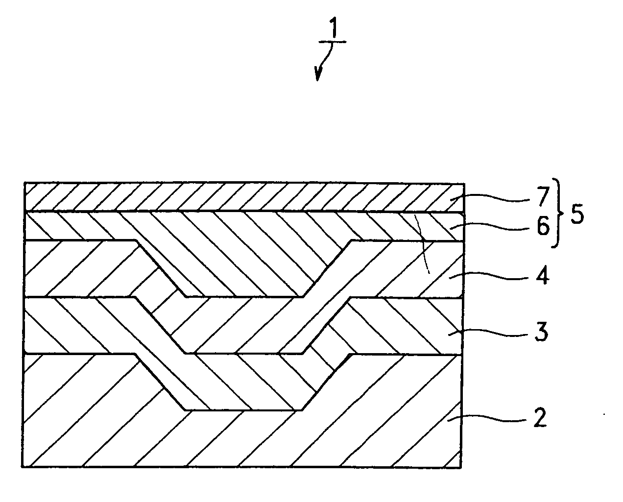
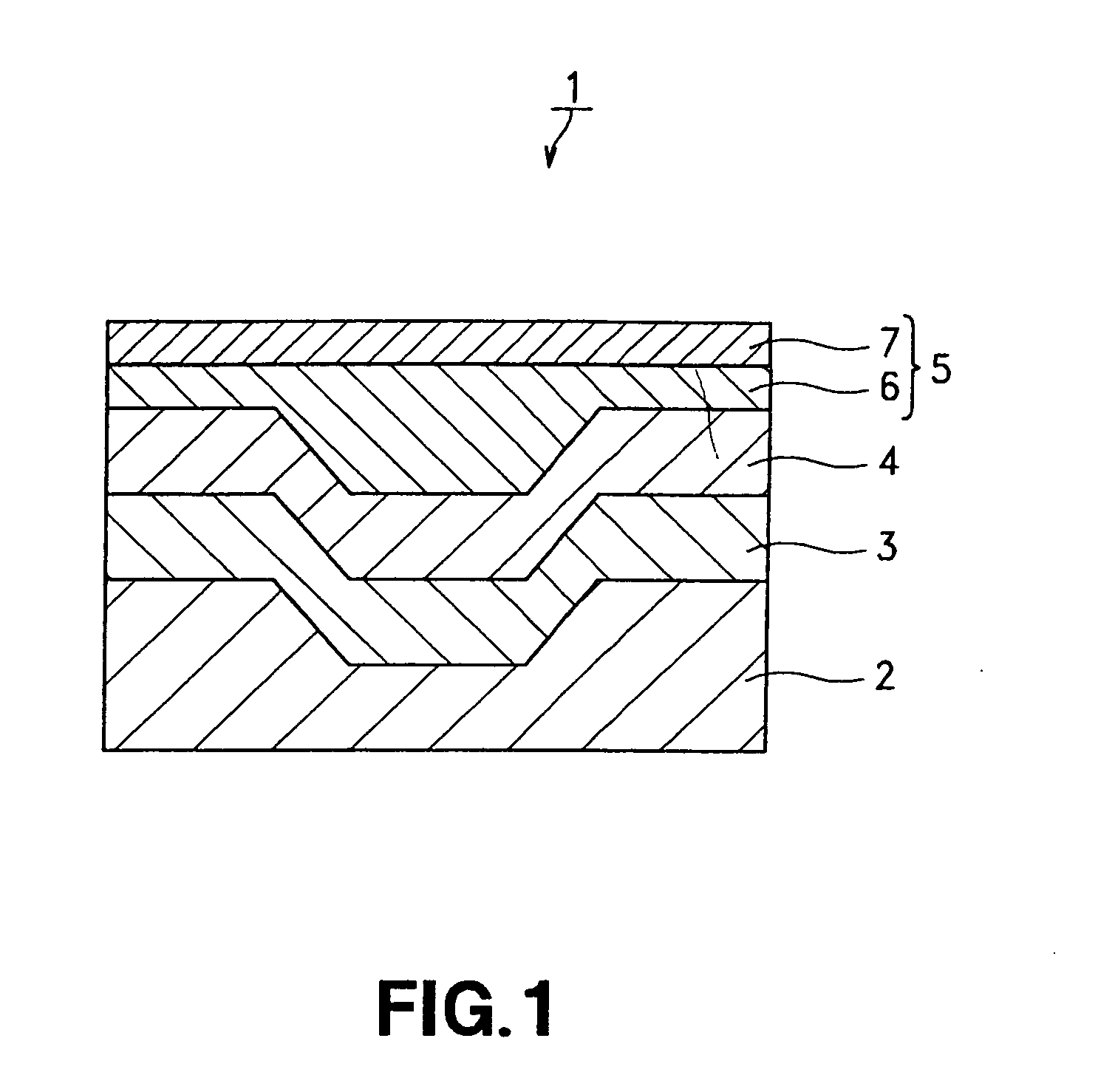
[0022] As FIG. 1 shows, the optical disc 1 according to this invention comprises a substrate 2, a reflecting layer 3, a recording layer 4, and a light-transmitting layer 5. The layers 3, 4 and 5 are provided on the substrate 2, laid one upon another, in the order they are mentioned. Light beams are applied to the recording layer 4 through the light-transmitting layer 5, to record and reproduce data signals on and from the recording layer 4.

[0023] The substrate 2 is made of a resin such as polycarbonate resin or amorphous polyolefin resin. The substrate 2 is one that is 0.3 mm thick or thicker.

[0024] The reflecting layer 3 is provided on the back of the recording layer 4 to reflect light applied to it. The layer 3 is made of, for example, Al or Al alloy.

[0025] The recording layer 4 is the layer on which data signals are recorded. In this embodiment, the layer 4...


PUM

PropertyMeasurementUnit
wavelengthaaaaaaaaaa
thicknessaaaaaaaaaa

Abstract

An optical disc comprising a substrate and a recording layer and a light-transmitting layer, laid on a substrate one upon the other in the order mentioned. A light beam is applied to the recording layer through the light-transmitting layer, to record and / or reproduce data on the disc. The light-transmitting layer is composed of at least two material layers laid one on the other and having different refractive indices. The disc is designed to set the spherical aberration caused by an objective lens that focuses the light beam used to record and / or reproduce data, at a value close to a minimum.

Description

TECHNICAL FIELD [0001] The present invention relates to an optical disc which has a light-transmitting layer, on which data signals have been recorded through the light-transmitting layer and from which the data signals recorded are reproduced. BACKGROUND ART [0002] Hitherto, optical discs have been used, each comprising a recording layer, a reflecting layer and the like, which are laminated upon another on a substrate. A light beam is applied to the recording layer of an optical disc, thus recording a data signal on the optical disc. Another light beam is applied to the recording layer, thereby reproducing the data signal recorded on the recording layer. It is demanded that the recording density of optical discs be increased so that as much data as possible may be recorded on each optical disc. A variety of techniques has been proposed to meet this demand. [0003] The recording density of optical discs, i.e., an increase in the storage capacity of each optical disc, can be achieved ...

Claims


Application Information

Patent Timeline
Patent Type & Authority Applications(United States)
IPC IPC(8): G11B7/00G11B7/24056G11B7/24067
CPCG11B7/24067G11B7/24056G11B7/252
Inventor YAMASAKI, TAKESHIYAMAMOTO, KENJIKASHIWAGI, TOSHIYUKI
Owner SONY CORP
Why Eureka
Try Eureka