Distraction tube with wire clamp

a technology of dislocation tube and wire clamping, which is applied in the field of external fixation system and method, can solve the problems of lack of flexibility, inability to adjust and/or pivot, and difficulty for physicians to achieve optimal clinical outcomes, and achieve the effect of greater flexibility in the positioning and placement of the fixation pin

Active Publication Date: 2017-02-16
STRYKER EURO OPERATIONS HLDG LLC
View PDF33 Cites 5 Cited by
  • Summary
  • Abstract
  • Description
  • Claims
  • Application Information

AI Technical Summary

Benefits of technology

[0008]The present invention improves upon existing mini-rails by allowing for greater flexibility in fixation pin clamping and placement. The systems and methods described h...

Problems solved by technology

Some existing fixation systems on the market have components that are static and do not allow for certain adjustment and/or pivoting.
Lack of flexibility in a system may restrict attachment to certain bone areas at certain angles as well as restrict motion of the portion of the body that the external fixation system is being attached to in order to correct.
Because of such lack of flexibility, such systems may make it more difficult for the physician to achieve an optimal clinical outcome.
Existing mini-rail systems are generally bulky, unnecessarily complex in ...

Method used


Image

  • Distraction tube with wire clamp
  • Distraction tube with wire clamp
  • Distraction tube with wire clamp

Examples


Embodiment Construction

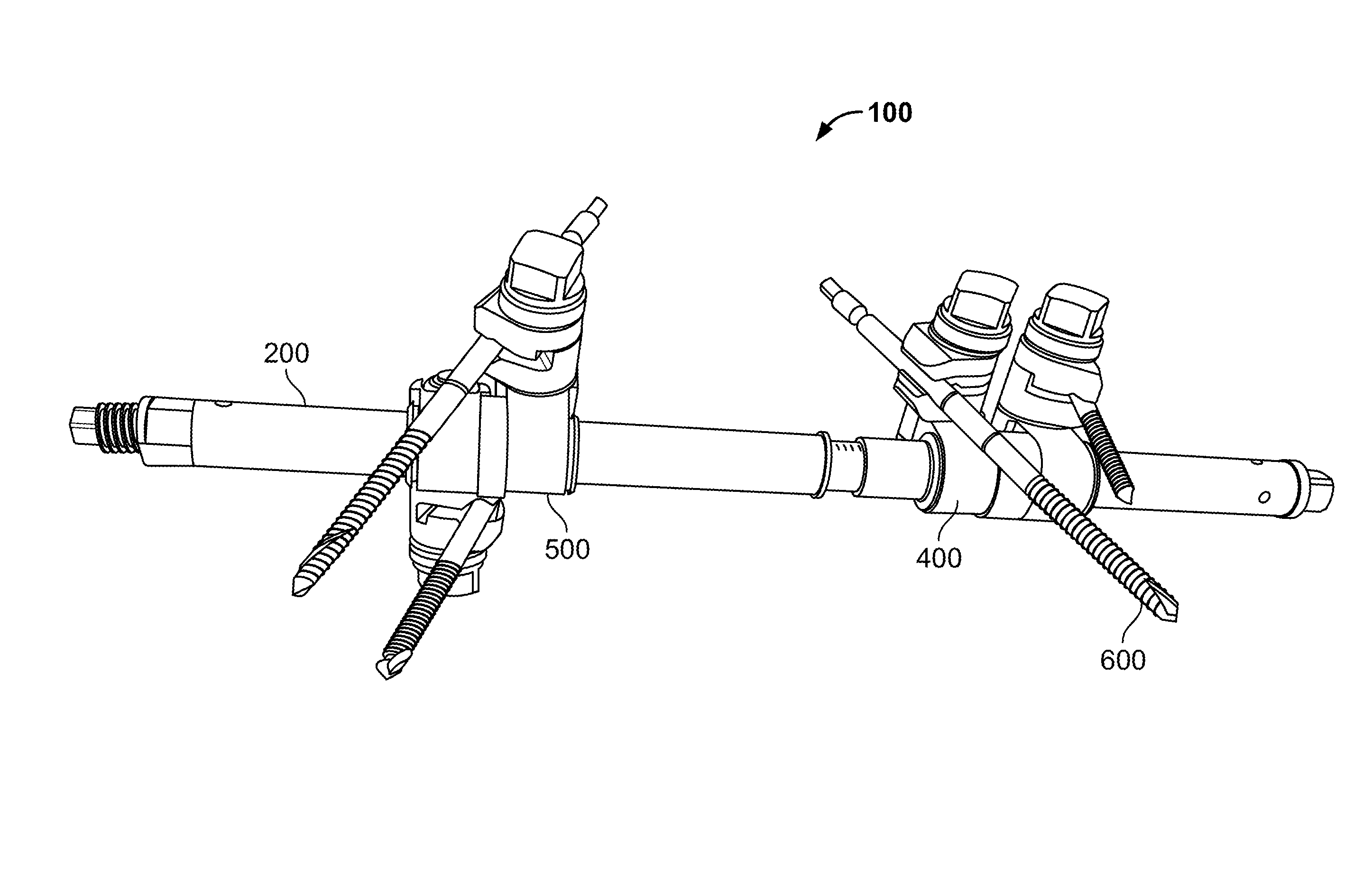
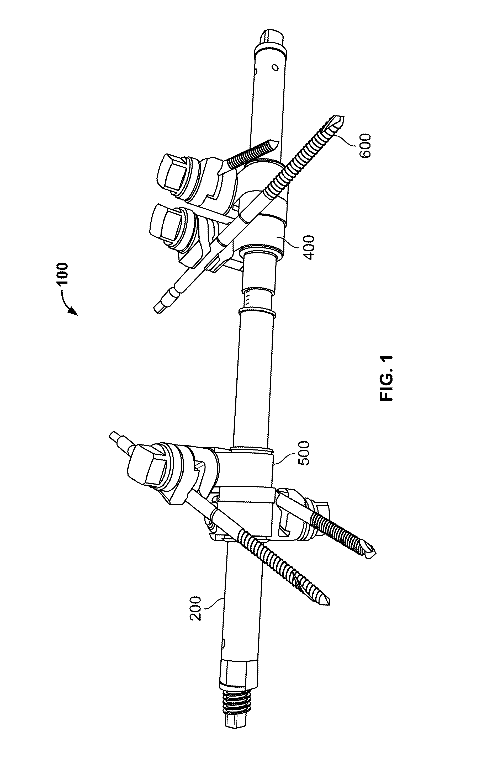
[0039]In FIG. 1 there is shown an embodiment of an external fixation system 100 having a distraction tube or telescoping rod 200, a first housing member 400, a second housing member 500, and a plurality of fixation pins 600 coupled to respective clamping portions of the first and second housing members 400, 500.

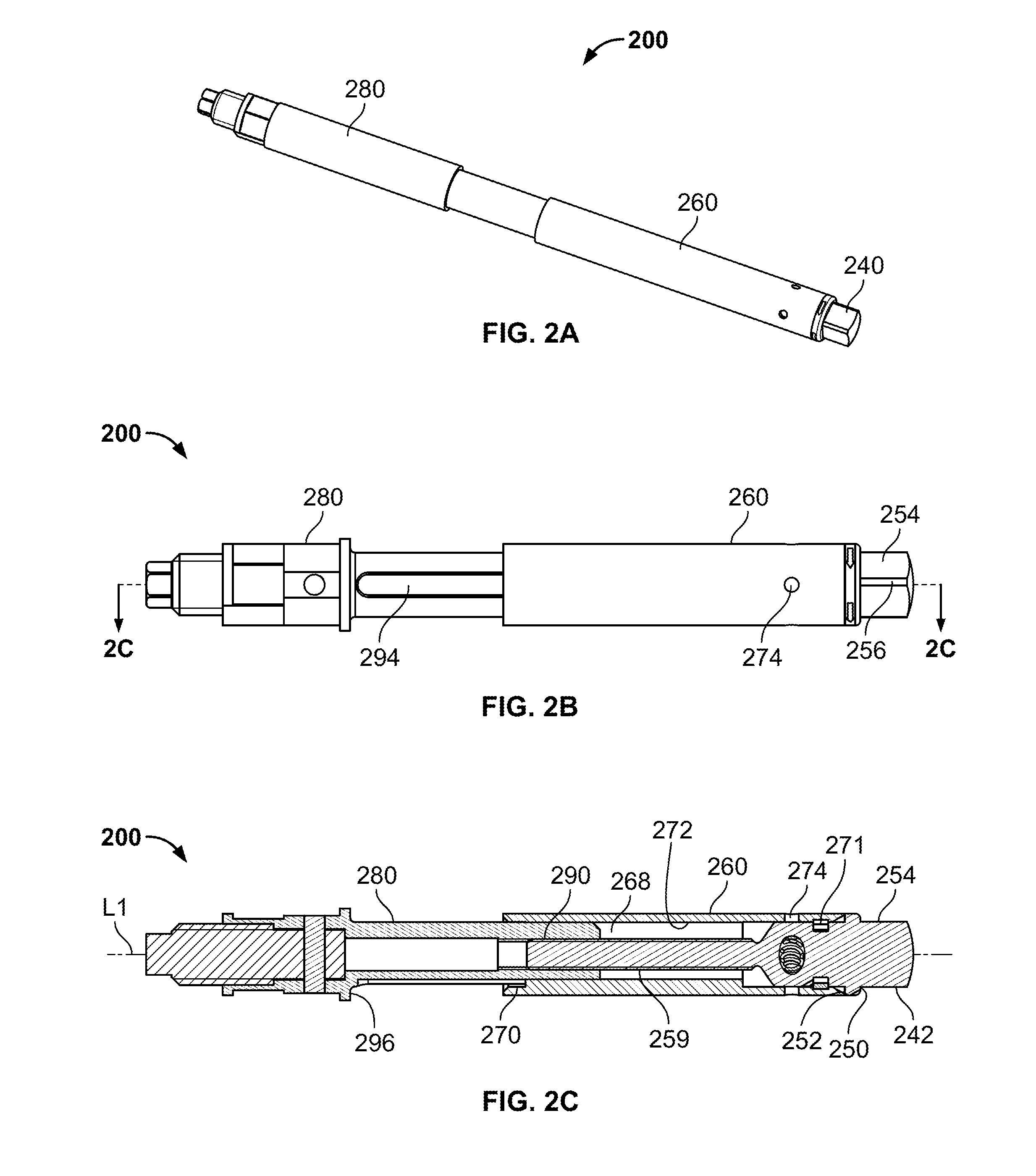
[0040]FIGS. 2A-2B are assembled views of distraction tube 200 having an actuation member 240, a first elongate tube member 260, a second elongate tube member 280, a spring clip 294, a detent 296 and a ball 298.

[0041]As shown in FIGS. 2C-2D, actuation member 240 includes an actuation portion 242, a base portion 244, an engagement portion 246 and a shaft portion 248. Actuation portion 242 projects outwardly in a distal direction from a distal end surface 250 of base portion 244. Engagement portion 246 projects outwardly in a proximal direction from a proximal end surface 252 of base portion 244. Engagement portion houses at least a portion of detent 296 and ball 298. Shaft port...


PUM


Abstract

Described herein are external fixation systems for correcting bone deformities in adjacent bones or fragments thereof. The systems herein include first and second elongate tubes that translate with respect to one another via rotation of an actuation member at an end of one of the rods. At least one housing member is coupled along a length of one of the tubes. The housing member includes at least clamping portion for clamping a portion of a fixation pin therein. When the housing member is in an unlocked state, the clamping portions can move in a variety of directions. When in a locked state, the housing member cannot move with respect to the tube that it is coupled to. The position and orientation of the fixation pin is also set. The locked and unlocked state of the housing member is determined by the positioning of a locking pin coupled to the housing member.

Description

CROSS-REFERENCE TO RELATED APPLICATIONS[0001]This application claims the benefit of the filing date of U.S. Provisional Application No. 62 / 203,174 filed Aug. 10, 2015, the disclosure of which is hereby incorporated by reference herein.FIELD OF THE INVENTION[0002]The present invention relates to external fixation systems and methods, and in particular relates to improved fixation pin positioning and orientation using dynamic housing members with clamping portions coupled to a telescoping body.BACKGROUND OF THE INVENTION[0003]Many different types of bone deformities can be corrected using external fixation systems. Such systems generally use rings, fixation plates, threaded rods or struts for manipulation, angulation, and translation of the deformities of bones.[0004]Some existing fixation systems on the market have components that are static and do not allow for certain adjustment and / or pivoting. Lack of flexibility in a system may restrict attachment to certain bone areas at certai...

Claims


Application Information

Patent Timeline
IPC IPC(8): A61B17/64
CPCA61B17/6466A61B2017/00991A61B17/6416A61B17/66
Inventor MANNANAL, SUBASH K.
Owner STRYKER EURO OPERATIONS HLDG LLC
Why Eureka
Try Eureka