Catheter assembly
a technology of catheter and assembly, which is applied in the direction of guide needles, medical devices, other medical devices, etc., can solve the problem of relatively easy warping of catheter, and achieve the effect of preventing warping
- Summary
- Abstract
- Description
- Claims
- Application Information
AI Technical Summary
Benefits of technology
Problems solved by technology
Method used
Image
Examples
first embodiment
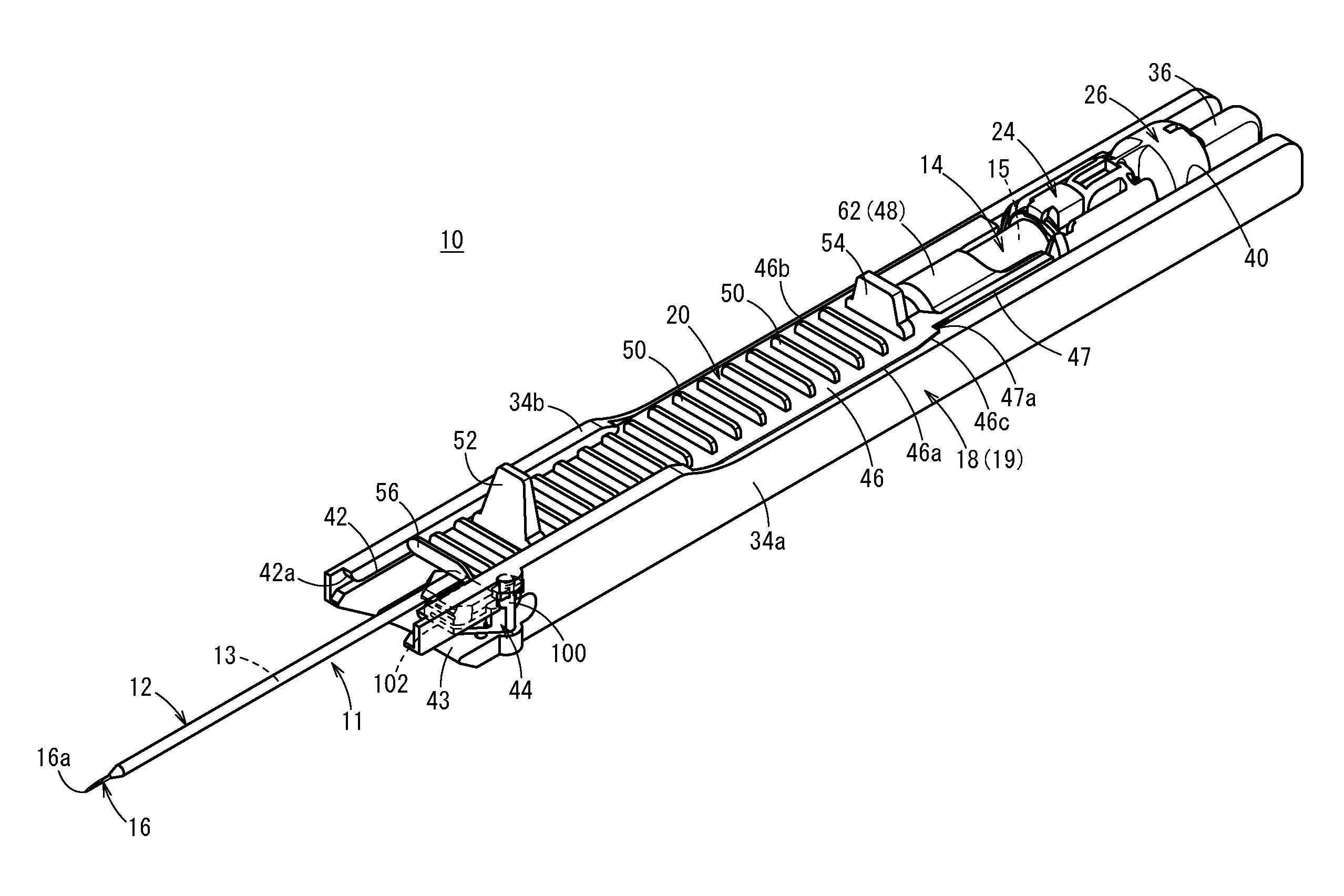
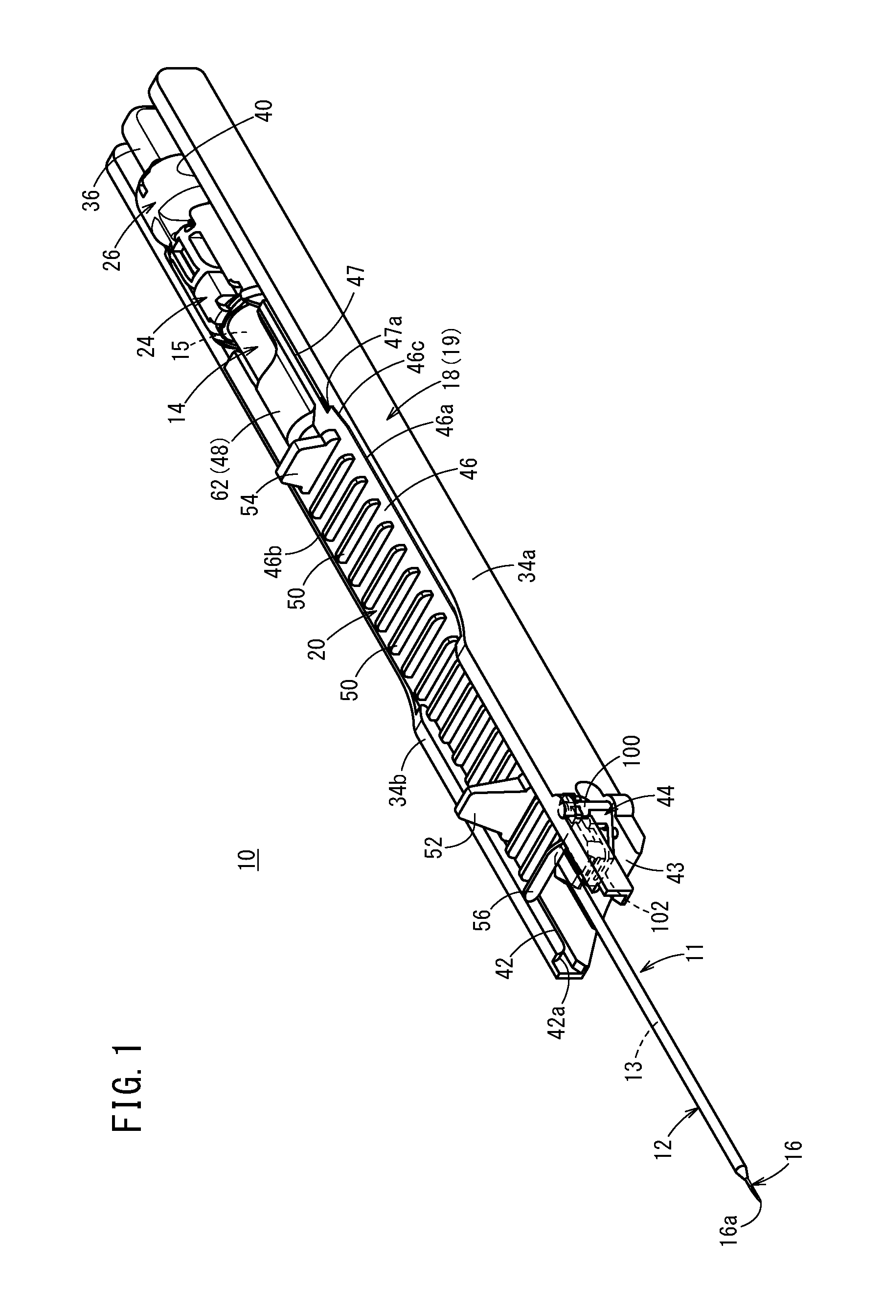
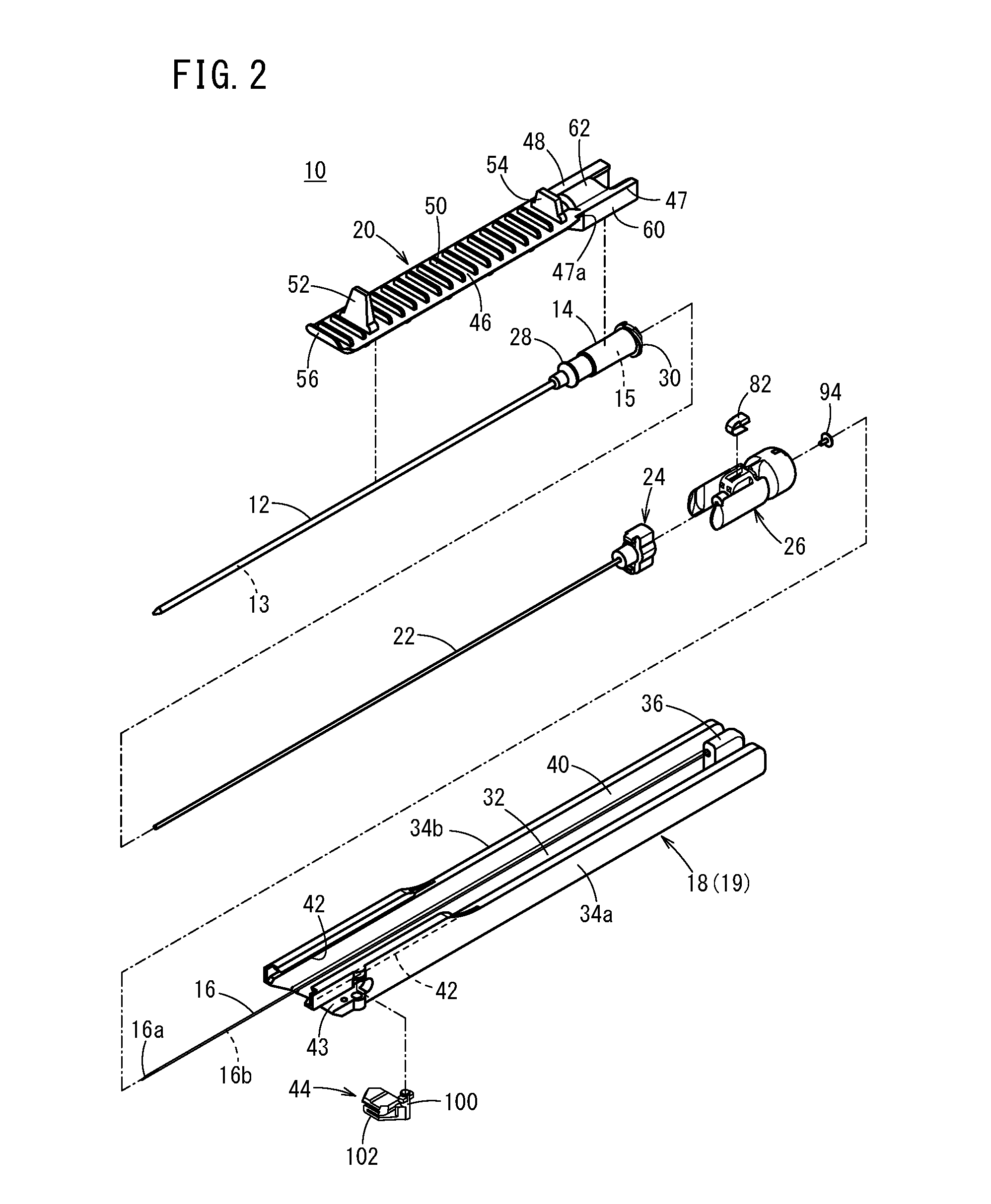
[0050]As illustrated in FIGS. 1 and 2, a catheter assembly 10 according to a first embodiment includes a catheter 12, a catheter hub 14 to fixe and hold the catheter 12, a hollow inner needle 16 inserted into the catheter 12, a needle hub 18 to fix and hold the inner needle 16, a catheter operation member 20 attached to an upper side of the catheter hub 14, a tube-like auxiliary member 22 inserted between the catheter 12 and the inner needle 16, an auxiliary member hub 24 to fix and hold the auxiliary member 22, and a needle protection member 26 connected to the catheter hub 14 and a proximal end of the auxiliary member hub 24.
[0051]In an initial state before use, the catheter assembly 10 has a multiple tube structure (multiple tube unit 11) in which the catheter 12, auxiliary member 22, and inner needle 16 are stacked sequentially from the outside. The catheter operation member 20 has a structure to directly hold the multiple tube unit 11. Additionally, in the initial state, the ca...
first modified example
[0117]Next, a catheter assembly 10A according to a first modified example will be described. Note that a reference sign same as the one used in the above-described embodiment has the same structure or the same function in the following description, and a detailed description therefor will be omitted.
[0118]A catheter assembly 10A according to the first modified example differs from the catheter assembly 10 in that a torsion spring 130 is adopted as the support member to support the catheter 12 as illustrated in FIG. 11. Furthermore, a needle hub 18A (housing 19A) of the catheter assembly 10A includes a housing portion 132 to arrange the torsion spring 130 instead of the above-described arrangement recessed portion 43.
[0119]The housing portion 132 slightly bulges outward in the width direction from the side wall 34a of the housing 19A and includes a spring housing chamber inside thereof (not illustrated). Furthermore, the housing portion 132 includes, on the lower side of the rail por...
second embodiment
[0125]Next, a catheter assembly 200 according to a second embodiment of the present invention will be described. In the catheter assembly 200, a shape of a needle hub 202 differs from a needle hub 18 of a catheter assembly 10 according to a first embodiment as illustrated in FIGS. 13 and 14. More specifically, the needle hub 202 includes a housing 204 and a pair of arms 212 projecting from the housing 204 in a distal end direction.
[0126]The housing 204 includes: a lower wall 206 having a pair of side portions 32a and a guide groove 32b; and a pair of side walls 208 projecting upward from both side portions of the lower wall 206, and forms a housing space 204a on an inner side of the lower wall 206 and the pair of side walls 208. A needle protection member 26 is housed in the housing space 204a of the housing 204 in the initial state. Meanwhile, the catheter assembly 200 does not include an auxiliary member 22 and an auxiliary member hub 24 described above, but needless to mention th...
PUM
 Abstract
Description
Claims
Application Information
 - R&D
- Intellectual Property
- Life Sciences
- Materials
- Tech Scout
- Unparalleled Data Quality
- Higher Quality Content
- 60% Fewer Hallucinations
Browse by: Latest US Patents, China's latest patents, Technical Efficacy Thesaurus, Application Domain, Technology Topic, Popular Technical Reports.
© 2025 PatSnap. All rights reserved.Legal|Privacy policy|Modern Slavery Act Transparency Statement|Sitemap|About US| Contact US: help@patsnap.com


