Flow through flange for a ship-to-ship cargo transfer flow line

Inactive Publication Date: 2017-02-16
BP CORP NORTH AMERICA INC
View PDF0 Cites 5 Cited by
  • Summary
  • Abstract
  • Description
  • Claims
  • Application Information

AI Technical Summary

Benefits of technology

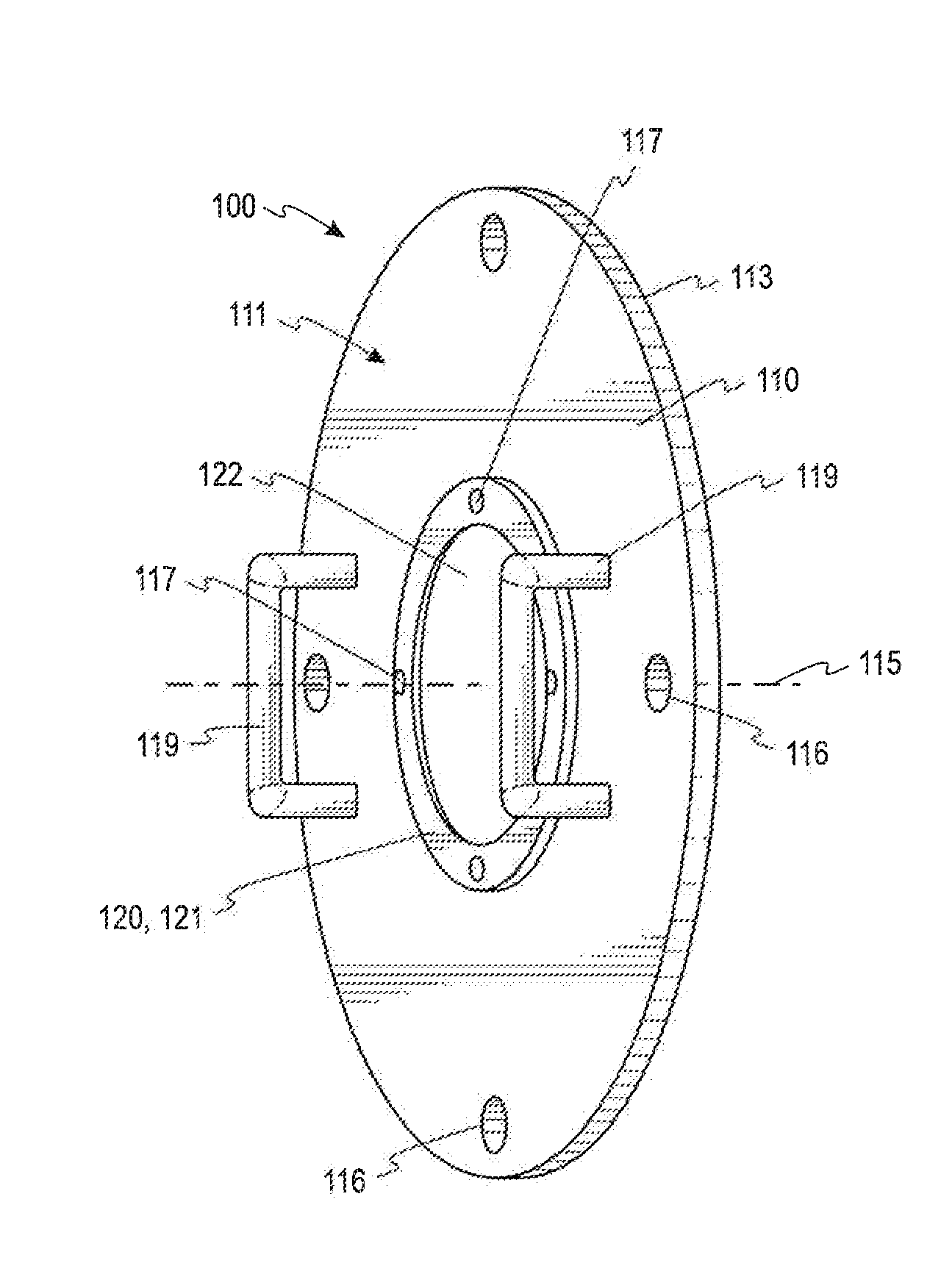
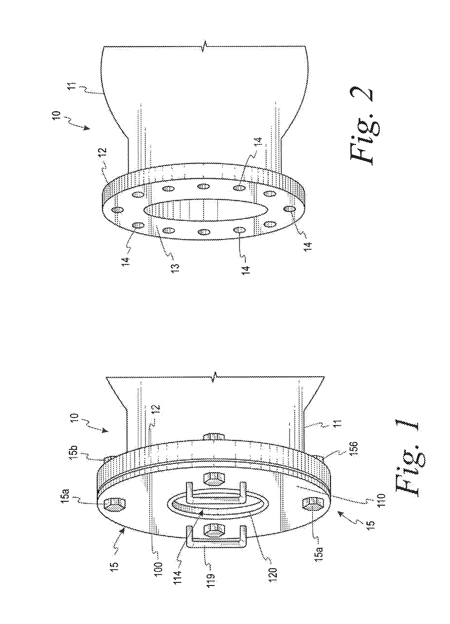
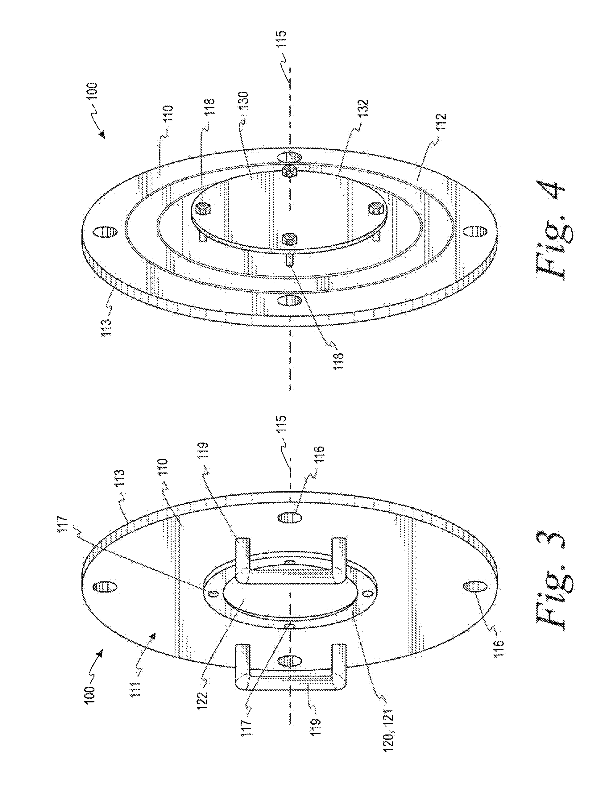
The patent describes a flange for mounting to an end of a ship-to-ship cargo transfer line for transporting hydrocarbon liquids. The flange has a base plate with an orifice and a blast plate that is axially spaced from the base plate. The blast plate is designed to inhibit the flow of hydrocarbon liquids and allow air to flow through the orifice. The patent also describes a system for draining a ship-to-ship cargo transfer line that includes a flexible hose and a connection flange, as well as a screen for capturing hydrocarbon liquids that flow through the flange. The technical effects of the patent include improved safety and efficiency in the transportation of hydrocarbon liquids and the prevention of environmental pollution.

Problems solved by technology

However, if the cargo storage tanks on the daughter ship are pressurized or a slug of trapped gas in the cargo storage tanks moves upward through the flow line, a small amount of the cargo (e.g., an atomized mist of hydrocarbons) may inadvertently be released from the lifted, open end of the flow line, thereby creating an undesirable pollution risk.

Method used


Image

  • Flow through flange for a ship-to-ship cargo transfer flow line
  • Flow through flange for a ship-to-ship cargo transfer flow line
  • Flow through flange for a ship-to-ship cargo transfer flow line

Examples


Embodiment Construction

[0024]The following discussion is directed to various exemplary embodiments. However, one skilled in the art will understand that the examples disclosed herein have broad application, and that the discussion of any embodiment is meant only to be exemplary of that embodiment, and not intended to suggest that the scope of the disclosure, including the claims, is limited to that embodiment.

[0025]Certain terms are used throughout the following description and claims to refer to particular features or components. As one skilled in the art will appreciate, different persons may refer to the same feature or component by different names. This document does not intend to distinguish between components or features that differ in name but not function. The drawing figures are not necessarily to scale. Certain features and components herein may be shown exaggerated in scale or in somewhat schematic form and some details of conventional elements may not be shown in interest of clarity and concis...


PUM


Abstract

flange (100) for mounting to an end of a ship-to-ship cargo transfer line for transporting hydrocarbon liquids, the flange comprising: a base plate (110) including an orifice having a central axis and an outer radius; a blast plate (130) coupled to the base plate and coaxially aligned with the orifice, wherein the blast plate (130) is axially spaced from the base plate (110); wherein the blast plate (130) has an outer radius greater than or equal to the outer radius of the orifice and is configured to impede the flow of the hydrocarbon liquids from the flow line through the orifice, and wherein the blast plate (130) is configured to allow the flow of air into the flow line through orifice.

Description

CROSS-REFERENCE TO RELATED APPLICATIONS[0001]This application claims the benefit of U.S. Provisional Patent Application No. 61 / 985,668 filed Apr. 29, 2014, which is incorporated herein by reference in its entirety.STATEMENT REGARDING FEDERALLY SPONSORED RESEARCH OR DEVELOPMENT[0002]Not applicable.BACKGROUND[0003]The disclosure relates generally to a flange for attaching to the terminal end of a ship-to-ship fluid transfer flow line. More particularly, the disclosure relates to a flow through flange that allows air to enter the fluid transfer line from the surrounding environment while preventing fluids within the transfer line from escaping the fluid transfer line into the surrounding environment.[0004]Fluid cargo such as crude oil, liquefied gas (LPG), and other hydrocarbon products is often transferred between two offshore vessels positioned alongside one another via ship-to-ship (STS) cargo transfer operations. In such operations, a fluid flow line or hose extends between the rec...

Claims


Application Information

Patent Timeline
IPC IPC(8): F16L23/00B67D9/00F16L55/07
CPCF16L23/003B67D9/00F16L55/07
Inventor DOOLITTLE, WILLIAM E.
Owner BP CORP NORTH AMERICA INC
Why Eureka
Try Eureka