Cable Assembly With Spine For Instrument Probe

Active Publication Date: 2017-02-16
TEKTRONIX INC
View PDF10 Cites 2 Cited by
  • Summary
  • Abstract
  • Description
  • Claims
  • Application Information

AI Technical Summary

Benefits of technology

[0006]Embodiments of the present invention provide an improved probe cable assembly for electrical test and measurement instruments that reduces mechanical stresses normally caused by the cable's resistance to bending and twisting. A pliable spine holds the cable assem

Problems solved by technology

The DUT often cannot be directly lined up with the instrument, causing the cable to bend or twist.
These stresses can compromise the probe's connection to the DUT or even damage the interface.
These solutions, however, require extra work when connecting the probe to the DUT.
Some solutions may even d

Method used


Image

  • Cable Assembly With Spine For Instrument Probe
  • Cable Assembly With Spine For Instrument Probe
  • Cable Assembly With Spine For Instrument Probe

Examples


Embodiment Construction

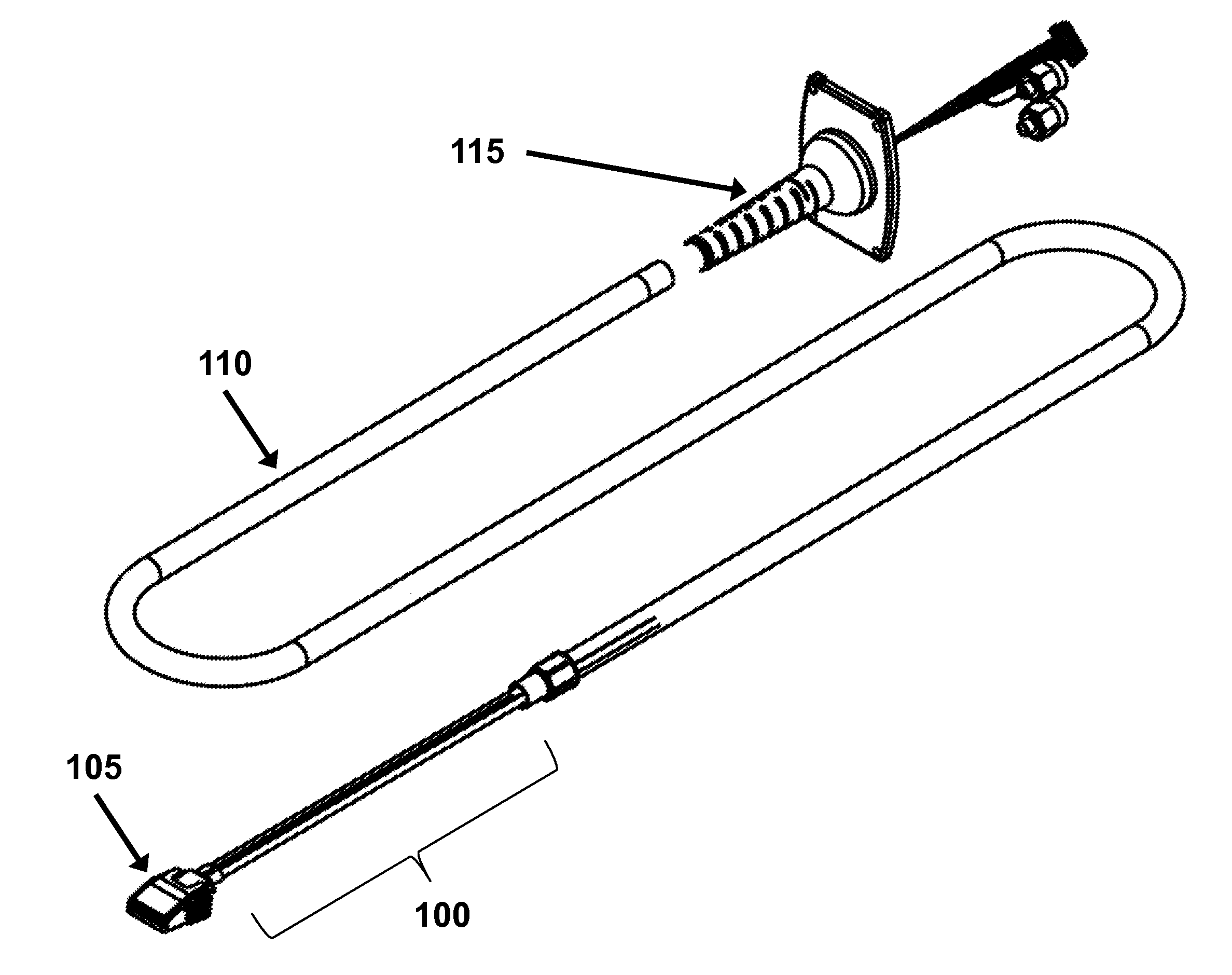
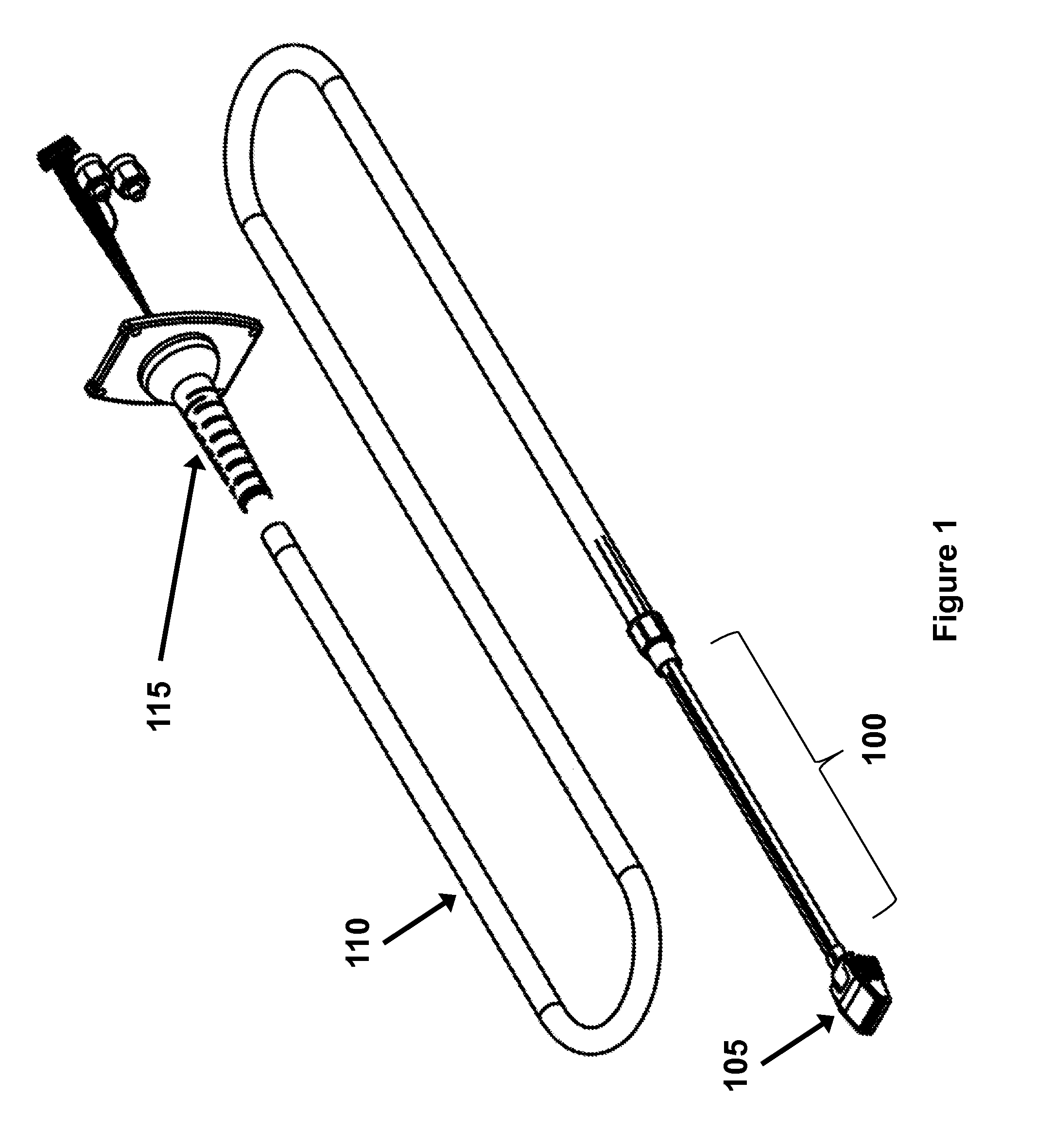
[0012]In order to measure signals in a device under test (“DUT”), test and measurement instruments such as oscilloscopes use a probe to connect to the device. The probe connects to the instrument via one or more signal cables. Usually, the DUT and instrument cannot be lined up perfectly, and the cables must be bent or twisted into position.

[0013]Unfortunately, the cables used in electrical test and measurement instruments typically resist bending and twisting. For example, coaxial cable (also referred to as “coax”) is commonly used because it shields the test and measurement signals from electrical interference and resists being crushed. Once it is bent or twisted, however, most coax will attempt to return to its original position. This imparts mechanical stresses to the interface between the probe and DUT.

[0014]These mechanical stresses can compromise the integrity of the connection, or worse, damage the interface. Both can occur easily when the probe is attached to a small or frag...


PUM


Abstract

Embodiments of the present invention provide an improved cable assembly for connecting an electrical test and measurement probe to a device under test. One end of the probe is connected to a device under test (“DUT”), while the other end is connected to the instrument through one or more cables. To prevent mechanical stresses to the probe-DUT interface caused by the cables' resistance to bending and twisting, embodiments of the improved cable assembly use one or more pliable spines to hold the cable assembly in position after it has been bent or twisted. This provides a more secure connection to the DUT and prevents damage to the probe-DUT interface. Each spine is anchored to the tip of the probe, and may be further secured by an outer housing or additional anchors. A flexible boot may surround the cable assembly and/or outer housing, further protecting the cables from damage. Alternatively, one or more spines may be placed inside the boot.

Description


Claims


Application Information

Patent Timeline
Owner TEKTRONIX INC
Why Eureka
Try Eureka