Vehicle lower portion structure

a technology of lower portion and vehicle, which is applied in the direction of superstructure connections, superstructure subunits, vehicle components, etc., can solve the problems of collision load transmission loss, and achieve the effect of efficient transmission

Active Publication Date: 2017-02-23
TOYOTA JIDOSHA KK
View PDF2 Cites 21 Cited by
  • Summary
  • Abstract
  • Description
  • Claims
  • Application Information

AI Technical Summary

Benefits of technology

[0015]With this configuration, compared to the configuration with no crossing as described above, the setting (design and manufacture of respective members, etc.) for contacting the rear end of the lower end portion of the front pillar reinforcement and the front end of the rocker reinforcement with each other as described above is facilitated.
[0016]As described above, in a vehicle lower portion structure according to the present disclosure, a collision load that is input from a vehicle front side to a front pillar can be efficiently transmitted to a rocker side.

Problems solved by technology

As a result, there is a possibility that the transmission loss of the collision load may occur due to deformation of the respective reinforcements around the spot welding points, or the like.

Method used


Image

  • Vehicle lower portion structure
  • Vehicle lower portion structure
  • Vehicle lower portion structure

Examples


embodiment

Supplementary Explanation of Embodiment

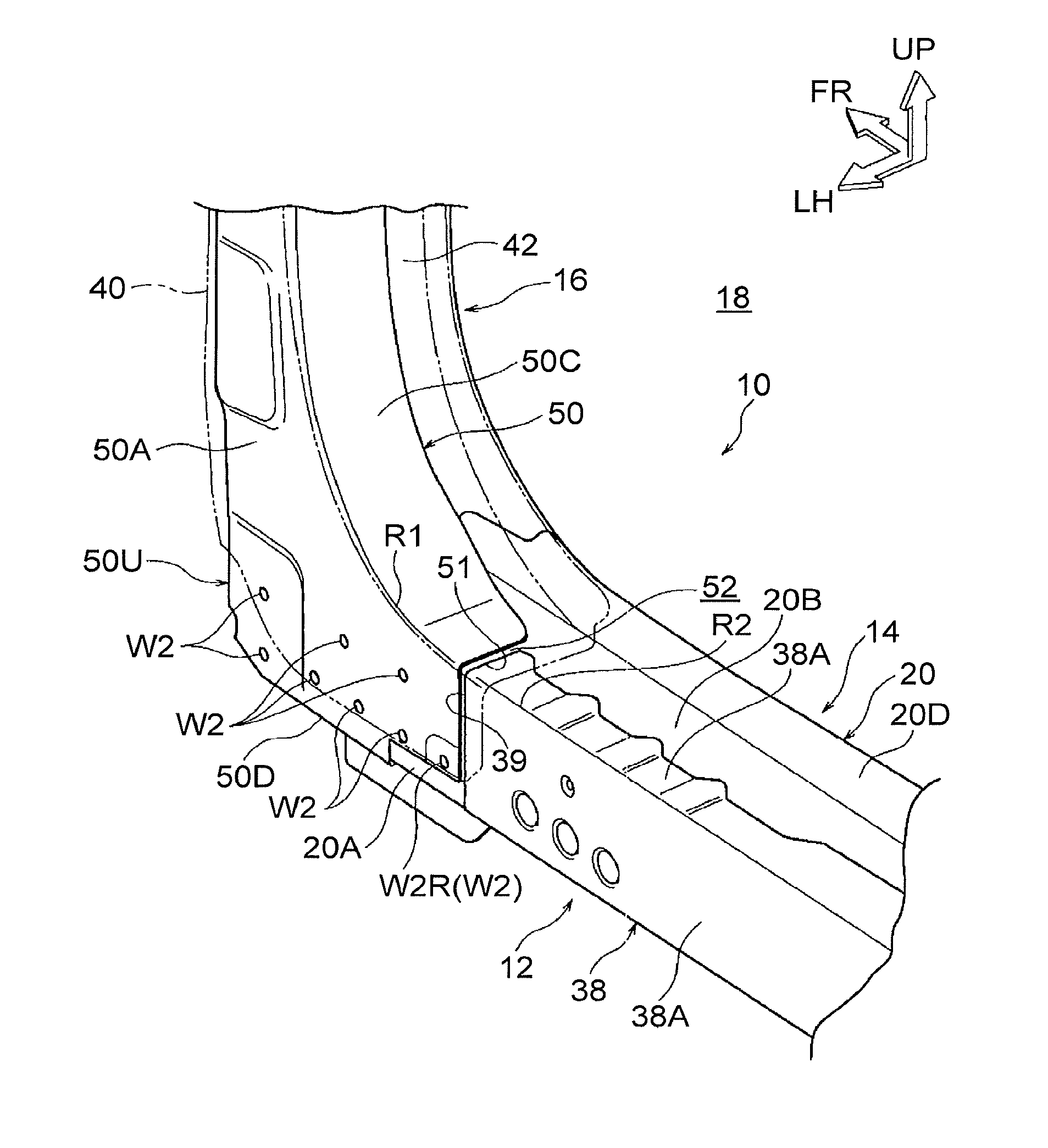
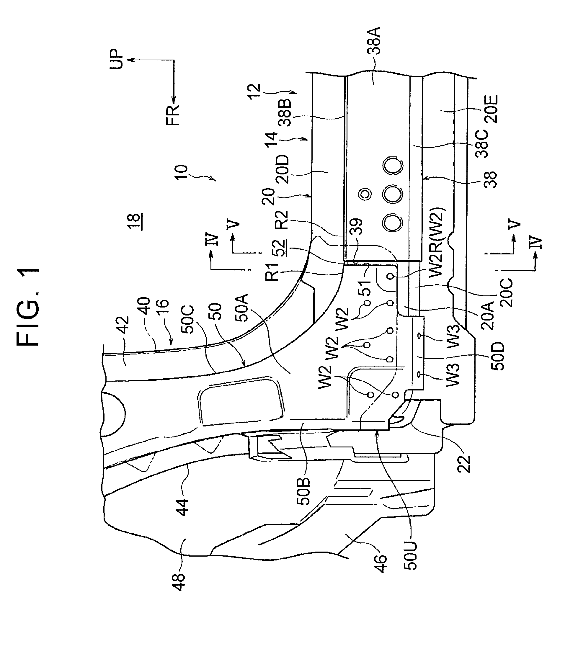
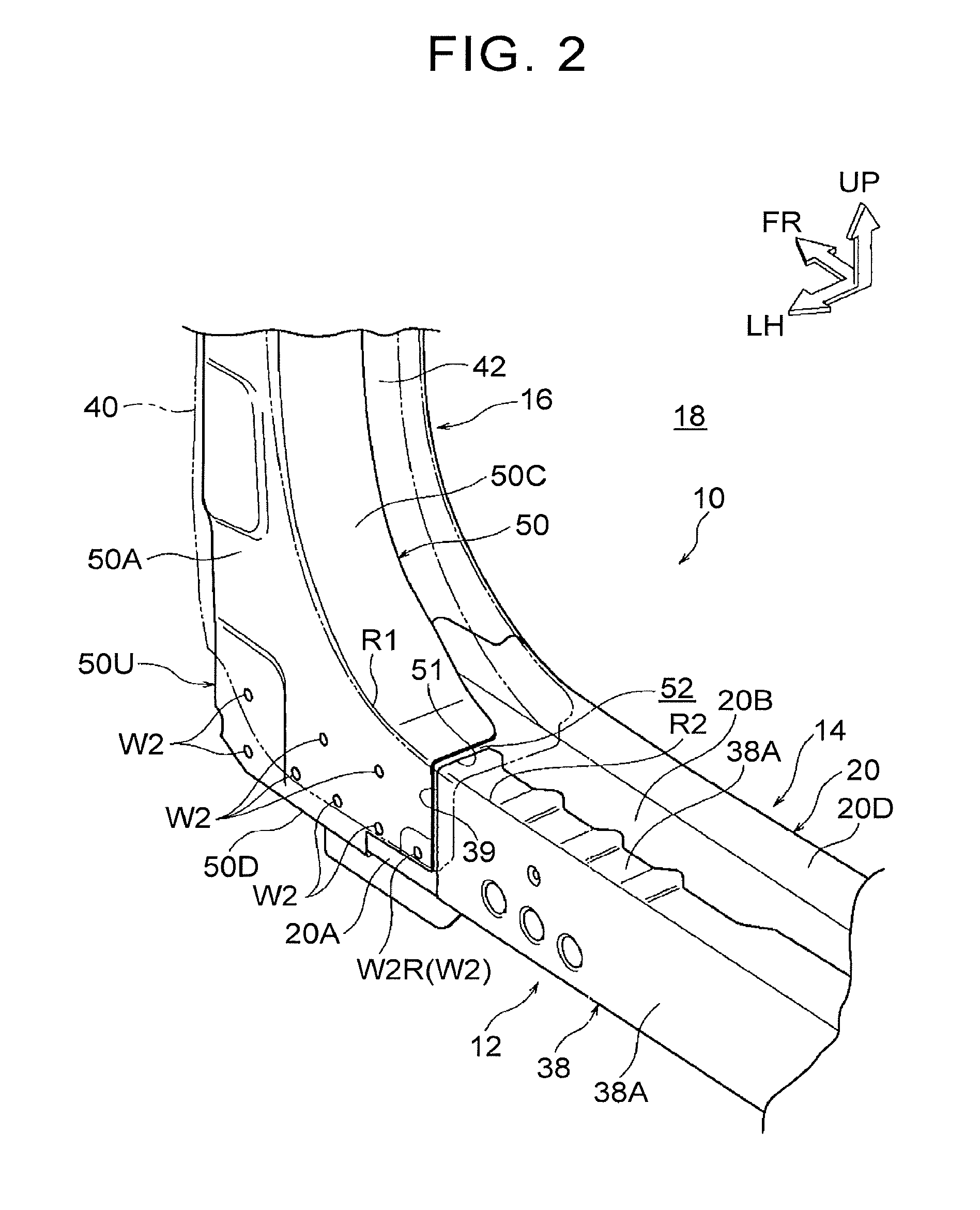
[0069]In the above-described embodiment, as a modification 70 shown in FIG. 15, part of a rear end 51 of an A-pillar RF 50 and part of a front end 39 of a rocker outer RF 38 may be configured to cross each other in a vehicle front view. In the modification 70, the rear end side of a rear wall portion 50C of the A-pillar RF 50 is bent in a crank shape in a vehicle front view so that a stepped portion 54 protruding toward the vehicle upper side is formed on the rear end side and the outer side in the vehicle width direction of the rear wall portion 50C. Further, the front end side of a side wall portion 38A of the rocker outer RF 38 is bent in a crank shape in a vehicle front view so that a stepped portion 56 protruding outward in the vehicle width direction is formed on the front end side and the upper end side of the side wall portion 38A. Consequently, part of the rear-end ridge line portion R1 side of the A-pillar RF 50 at the rear end 51 and...


PUM


Abstract

A vehicle lower portion structure includes a front pillar reinforcement provided to a front pillar and having a lower end portion joined to a panel forming a rocker; and a rocker reinforcement provided to the rocker, joined to the panel, and having a front end that is disposed to face a rear end of the lower end portion from a vehicle rear side, wherein when a collision load is input from a vehicle front side to at least the front pillar, the rear end comes in contact with the front end.

Description

INCORPORATION BY REFERENCE[0001]The disclosure of Japanese Patent Application No. 2015-164047 filed on Aug. 21, 2015 including the specification, drawings and abstract is incorporated herein by reference in its entirety.BACKGROUND[0002]1. Technical Field[0003]The present disclosure relates to a vehicle lower portion structure and, in particular, relates to a structure of a joint portion between a front pillar and a rocker.[0004]2. Description of Related Art[0005]In a vehicle side structure described in Japanese Patent Application Publication No. 2015-058749 (JP 2015-058749 A), a lower end portion of a front pillar outer reinforcement and a front end portion of a rocker outer reinforcement are disposed to overlap each other in a vehicle side view. As a related art, there is one described, for example, in Japanese Patent Application Publication No. 2006-205901 (JP 2006-205901 A).[0006]In the vehicle side structure described above, the lower end portion of the front pillar outer reinfo...

Claims


Application Information

Patent Timeline
Patent Type & Authority Applications(United States)
IPC IPC(8): B62D25/02B62D25/04
CPCB62D25/04B62D25/025B62D25/08B62D25/2036B62D27/023
Inventor SHIROOKA, MASAKAZUMATSUMOTO, YOHSUKE
Owner TOYOTA JIDOSHA KK
Why Eureka
Try Eureka