
Double-regulated turbine, installation for converting hydraulic energy and process for the rehabilitation of a double-regulated turbine

a technology for converting hydraulic energy and double-regulated turbines, which is applied in the direction of sustainable manufacturing/processing, climate sustainability, and final product manufacturing, etc., can solve the problems of deteriorating blades or hubs, affecting the performance of turbines, and not solving cavitation problems

Active Publication Date: 2017-03-02
GE RENEWABLE TECH
View PDF8 Cites 3 Cited by
  • Summary
  • Abstract
  • Description
  • Claims
  • Application Information

AI Technical Summary

Benefits of technology

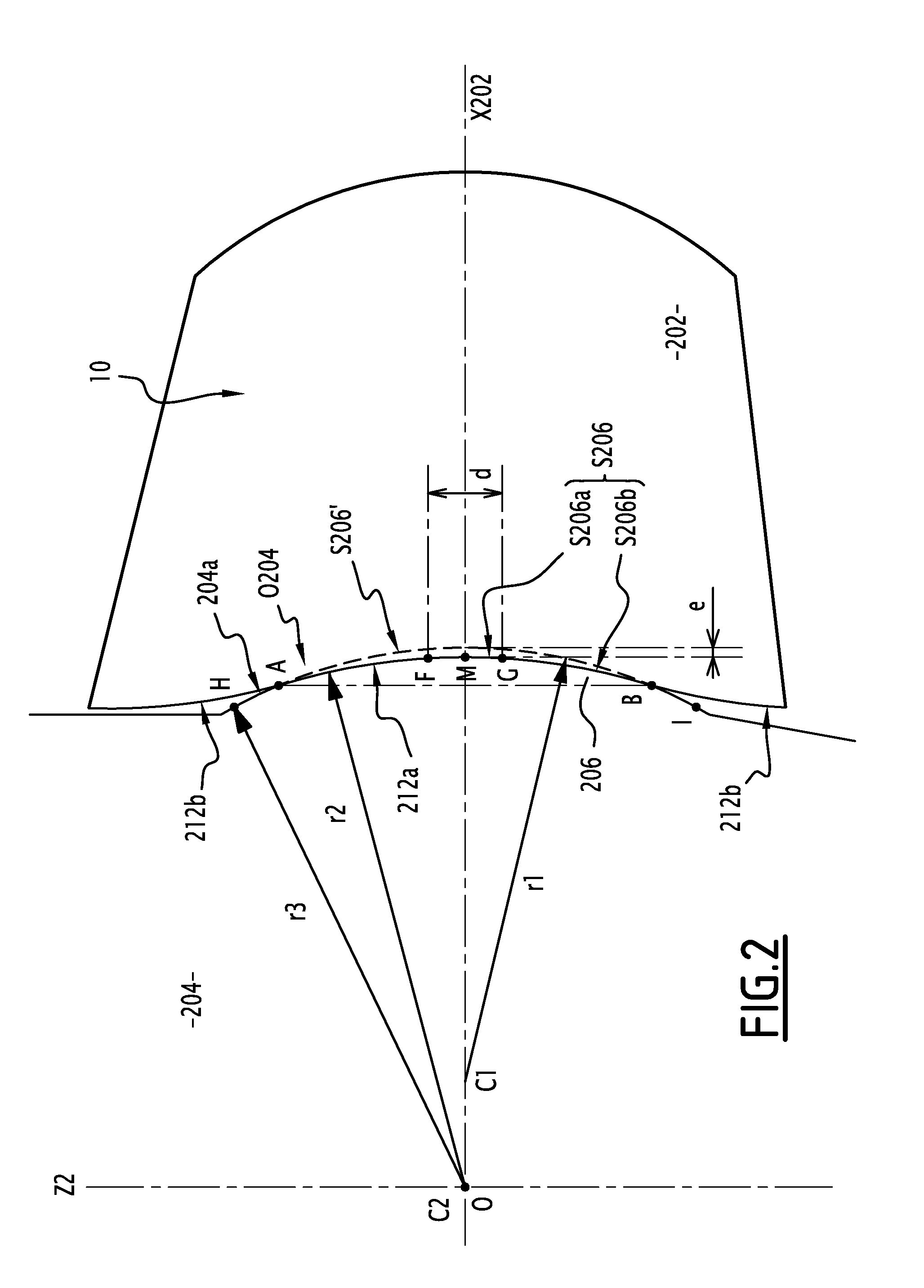
The invention makes the attachment surface of the hub flatter, which results in slower water flow and lower associated depression. This reduces the acceleration of water flow and improves the efficiency of the hub.

Problems solved by technology

Cavitation has a negative effect on the turbine performance and may deteriorate the blades or the hub over time.
Although the solutions mentioned here-above work efficiently for reducing cavitation in the gaps between the hub and the blades, they do not solve the problem of cavitation due to the spherical geometry of the hub.

Method used


Image

  • Double-regulated turbine, installation for converting hydraulic energy and process for the rehabilitation of a double-regulated turbine
  • Double-regulated turbine, installation for converting hydraulic energy and process for the rehabilitation of a double-regulated turbine
  • Double-regulated turbine, installation for converting hydraulic energy and process for the rehabilitation of a double-regulated turbine

Examples


Embodiment Construction

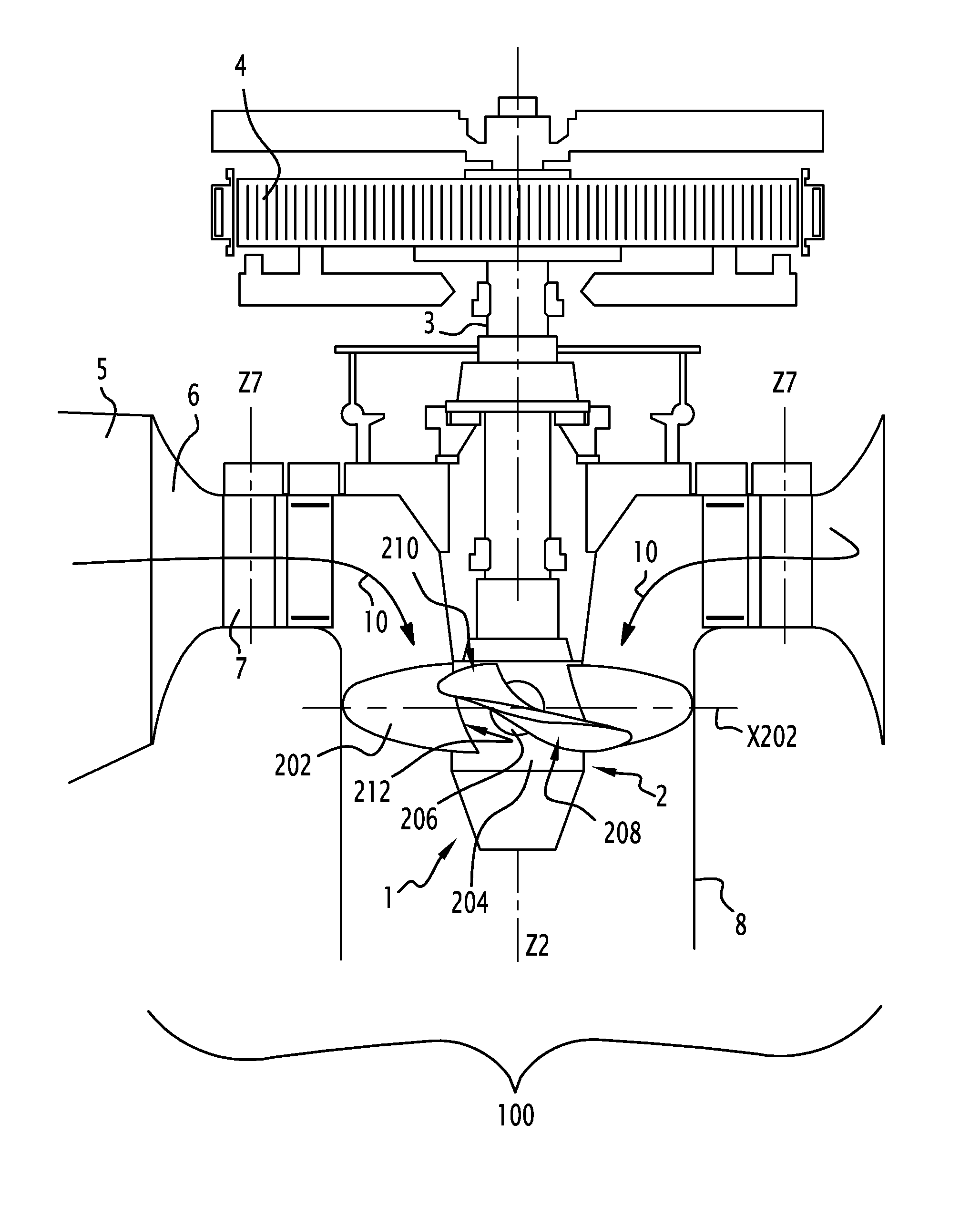
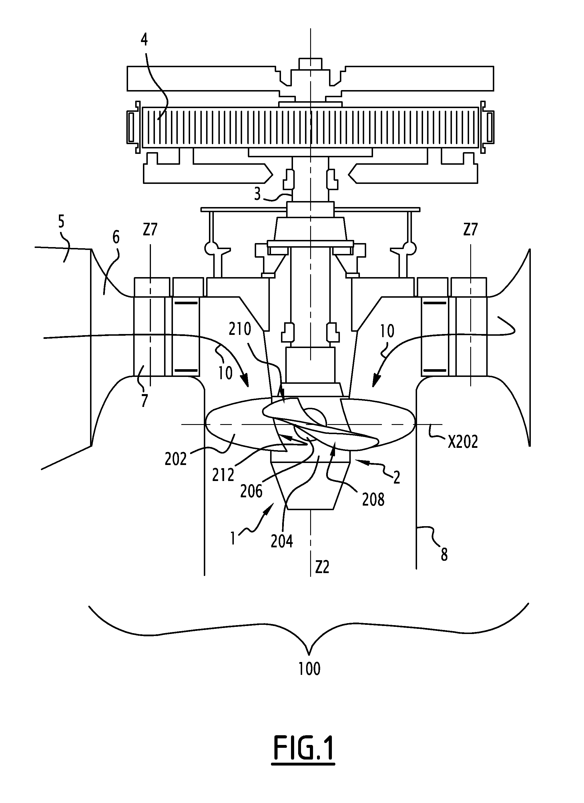
[0016]On FIG. 1 is represented an installation 100 for converting hydraulic energy into electrical energy. The installation 100 includes a Kaplan turbine 1 having a wheel 2 adapted to rotate around a vertical rotation axis Z2 under the action of a forced water flow 10 coming from a non-represented reservoir. A shaft 3 supports the wheel 2 and is coupled to a generator 4 which delivers an alternative current to a non-represented electricity power grid. The installation 100 may also convert hydraulic energy into mechanical energy for operating any mechanical device.

[0017]A penstock 5 enables supplying the wheel 2 with the forced water flow 10. It extends from the reservoir to a volute 6 equipped with a distributor. The distributor includes guide blades 7 that may be pivoted around an axis Z7 parallel to Z2 so as to adjust the flow rate of the water flow 10 circulating through the turbine 1. This constitutes a first level of regulation.

[0018]A draft tube 8 is arranged downstream of the...


PUM


Abstract

The double-regulated turbine comprises a spherical hub, adapted to rotate around a first rotation axis, and blades, which are each able to be swivelled relative to the hub around a second rotation axis, transversal to the first rotation axis, by respective coupling flanges that are mounted fixedly on the spherical hub and that include each an attachment surface for a corresponding blade. The attachment surface of the coupling flanges includes a flat portion.

Description

TECHNICAL FIELD[0001]Embodiments of the present invention relate to a double-regulated turbine, to an installation for converting hydraulic energy into mechanical or electrical energy comprising such a turbine and to a process for the rehabilitation of a double-regulated turbine.BACKGROUND[0002]In the field of hydraulic energy conversion, it is known to use a turbine for converting hydraulic energy into mechanical energy or electrical energy. Double-regulated turbines are particularly suited to low water falls, with a height which does not exceed 80 m. Double-regulated turbines are also adapted to strong or variable flow rates.[0003]A double-regulated turbine includes a spherical hub supporting several blades that involve, in operation, the rotation of the spherical hub around a rotation axis thanks to the difference of water pressure generated between the pressure-side surface and the suction-side surface of the blades.[0004]The blades may be each swiveled relative to the hub so as...

Claims


Application Information

Patent Timeline
Patent Type & Authority Applications(United States)
IPC IPC(8): F03B3/06F03B13/10
CPCF03B3/06F05B2230/60F05B2220/32F03B13/10F03B11/04F03B13/105Y02E10/20Y02P70/50F03B3/123F05B2230/80
Inventor PHAN, HAI TRIEU
Owner GE RENEWABLE TECH
Learn More