Microimpactor system having optimized impactor spacing

a technology of impactors and micro-pillars, which is applied in the direction of colloidal chemistry, separation processes, filtration separation, etc., can solve the problems of less than desirable particle capture efficiency of such micro-pillar devices, and achieve the effect of reducing the efficiency of device collection and operating very efficiently

Inactive Publication Date: 2005-09-22
Q21 CORPORATION
View PDF14 Cites 4 Cited by
  • Summary
  • Abstract
  • Description
  • Claims
  • Application Information

AI Technical Summary

Benefits of technology

[0007] It has unexpectedly been found that the spacing between adjacent microimpactors, both within a single row and between adjacent rows, has a very significant impact on the collection efficiency of the device. In particular, the spacing specified herein allows the microimpactor system to operate very efficiently at lower pressure drops than the micropillar system described in U.S. Pat. No. 6,110,247. Additionally, it has been found that the specified microimpactor spacing often enables a far greater proportion of particles within the desired size range to be collected, for a given number of microimpactors within the array, than the micropillar system of U.S. Pat. No. 6,110,247. As discussed more fully below, this effect is believed to be due to (1) lesser acceleration of the fluid as it passes between adjacent microimpactors and (2) the existence of quiescent zones downstream from each microimpactor, which allow for particle collection to occur on the downstream side of the microimpactors. The spacing described herein also provides advantages in interrogating the system for analysis of the captured particles, and in cleaning and / or recovering captured particles.

Problems solved by technology

In addition particle capture efficiency with such micropillar devices is often less than desirable, because particles tend to bounce off of micropillar surfaces (in part due to high impact velocities).

Method used


Image

  • Microimpactor system having optimized impactor spacing
  • Microimpactor system having optimized impactor spacing

Examples


Embodiment Construction

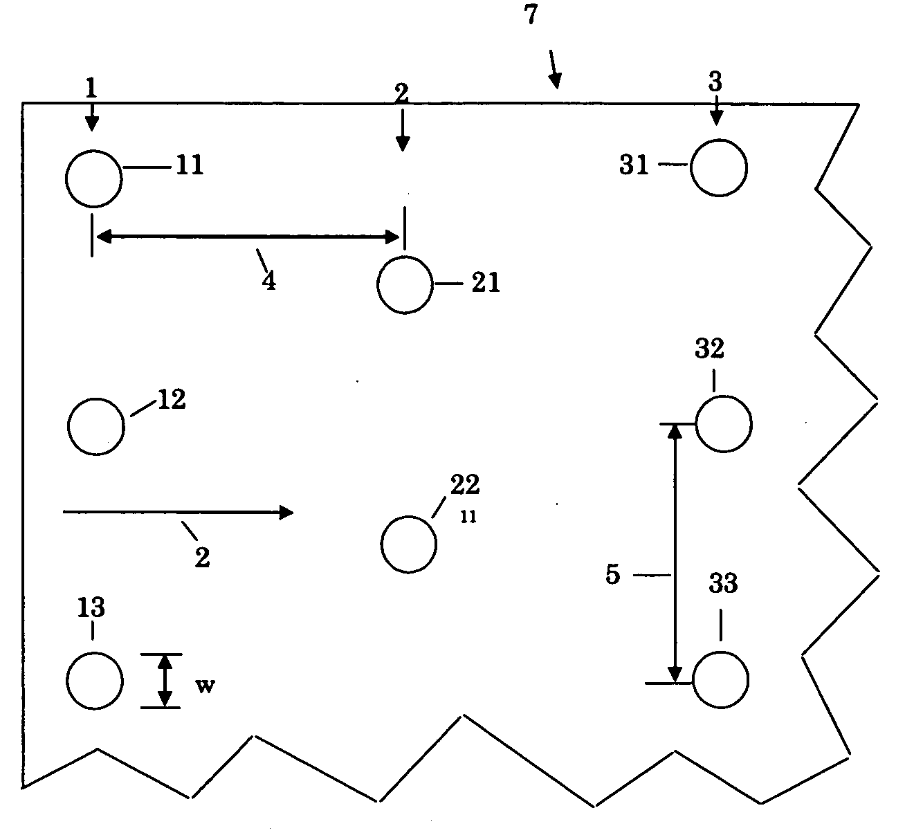
[0009] Microimpactor systems of the general designs described in U.S. Pat. No. 6,110,247 to Birmingham et al. and copending United States patent application of Faulkner et al., entitled “Microimpactor System for Collection of Particles From a Fluid Stream”, filed on even date herewith, are useful herein (both incorporated herein by reference), provided that such designs are so modified as to provide the inter-impactor spacing described herein. In general, the microimpactor system includes a plurality of microimpactors arranged into a series of rows to form a two-dimensional array. The microimpactor system can be produced from a single piece of material, as described in U.S. Pat. No. 6,110,247, using, for example, micromachining or deep ion etching methods. Preferably, the microimpactor system is made using a sheet architecture approach described in the copending application of Birmingham et al. described above. In the sheet architecture approach, rows of microimpactors are defined b...


PUM

PropertyMeasurementUnit
widthaaaaaaaaaa
heightsaaaaaaaaaa
heightsaaaaaaaaaa

Abstract

A microimpactor device for separating particles from a fluid stream includes a plurality of microimpactor in a two-dimensional array. Individual microimpactors are separated by a distance of about 3 to 20 times the microimpactor width. This spacing provides a device that operates well at low pressure drops across the device. Particles borne in a fluid stream tend to accumulate on both the front and rear sides of the microimpactors, thereby increasing the efficiency of the device.

Description

BACKGROUND OF THE INVENTION [0001] This invention relates to apparatus and methods for separating particulate matter (solid particles and / or liquid droplets) from a fluid stream. [0002] It is often desirable to remove particulate matter from a fluid stream. For example, it may be desired to simply cleanse the fluid of the particulate matter, or at least reduce the concentration of the particulate matter in the stream. In other instances, the goal is to capture a certain size range of particulate matter for analysis and / or characterization. Sometimes, the aim is to simply concentrate the particulate matter so that it can be used in some way. [0003] A large number of devices exist for this purpose. These include various types of filters, cyclones, electrostatic precipitators, among other devices. For removing very small particulate matter, such as aerosol particles and microorganisms, from a gas stream, various types of virtual cyclones and virtual impactor devices have been devised. ...

Claims


Application Information

Patent Timeline
Patent Type & Authority Applications(United States)
IPC IPC(8): B01D45/00B01D45/08
CPCB01D45/08Y10S55/39Y10S55/25
Inventor SHEKARRIZ, ALIREZATAYLOR, DANIELLE LYNNBIRMINGHAM, JOSEPH GERARD
Owner Q21 CORPORATION
Why Eureka
Try Eureka