Aircraft turbine engine air intake duct

a technology of air intake duct and turbine engine, which is applied in the direction of machines/engines, combustion-air/fuel-air treatment, transportation and packaging, etc., can solve the problems of insufficient effectiveness of solution, though functional, and the disturbance of boundary layer shedding that cannot be provided by a device of this type, so as to reduce the distortion in the compressor region, and reduce the effect of shedding

Active Publication Date: 2019-06-11
SN DETUDE & DE CONSTR DE MOTEURS DAVIATION S N E C M A
View PDF13 Cites 0 Cited by
  • Summary
  • Abstract
  • Description
  • Claims
  • Application Information

AI Technical Summary

Benefits of technology

[0009]The aim of several embodiments of the present invention is therefore to propose a system that makes it possible to reduce shedding of flows in the air intake duct in a targeted manner and thus to reduce the distortion in the region of the compressor whilst having the least possible impact on operability and efficiency.
[0011]Embodiments of the present invention thus propose a simple, effective and economical solution.

Problems solved by technology

However, the complex shape of the aforementioned duct brings about distortions in the air flow that supplies the gas generator, which has a negative impact on the performance and operability of the turbine engine.
Unfortunately, it appears that this solution, though functional, would not be effective enough in this type of design.
Indeed, the duct opens very widely in the region of the deflection, and the disturbances necessary for limiting shedding of the boundary layer cannot be provided by a device of this type.
However, devices of this type are complex and require elements for circulating the air, by means of suction or blowing, to be installed in a compartment of the nacelle near to the duct.

Method used


Image

  • Aircraft turbine engine air intake duct
  • Aircraft turbine engine air intake duct
  • Aircraft turbine engine air intake duct

Examples


Embodiment Construction

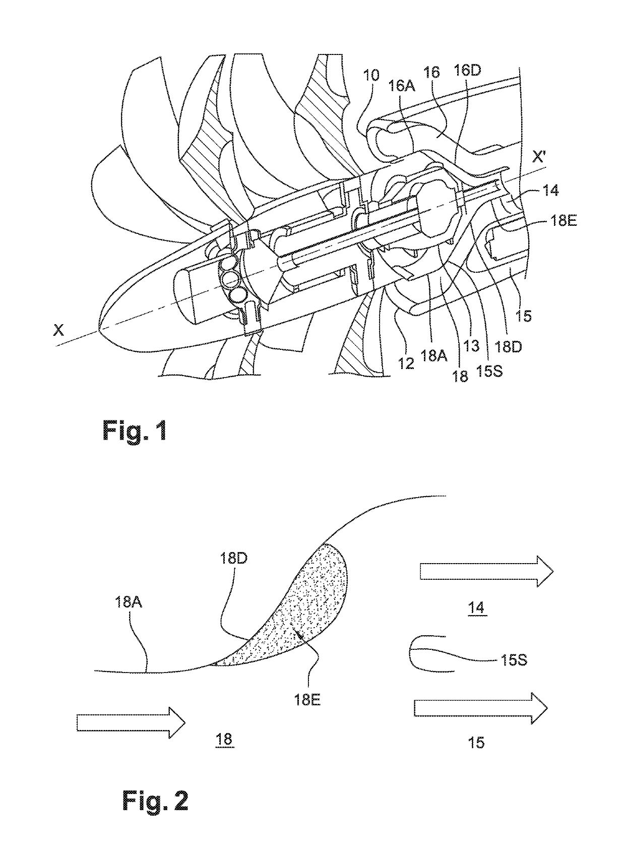
[0026]Reference will first be made to FIG. 1, which shows the front of an example open rotor engine in axial section with a front three-quarter view. The turbine engine comprises two counter-rotating propellers 11 at the front, driven by an engine located in the downstream extension of the axis of the propeller doublet 11. Immediately downstream, two air intakes 10 and 12 on the nacelle supply the gas generator (not shown in the figure) with air. The air intakes 10 and 12 are located on either side of the casing 13—above and below in this case—in which the mechanism for driving and controlling the propellers of the doublet 11 is accommodated. The intakes 10 and 12 communicate with two air intake ducts 16 and 18 having an oblong cross section. These two ducts 16 and 18 converge to a single annular channel 14 that is downstream of said casing 13 and forms the channel 14 for supplying the gas generator with air. Since the two intakes 10 and 12 are radially remote from the engine axis X...


PUM


Abstract

Air intake duct for supplying air to a turbine engine gas generator, in particular an aircraft turbine engine, extending axially between the air intake and the gas generator and having a deflection which may cause shedding of the boundary layer formed by the air flow along the wall of the duct, wherein said air intake duct comprises a guiding element located in the duct and designed to guide the air along the wall of the duct to a portion having the deflection, said guiding element extending transversely to the direction of the flow of air and having at the ends thereof two end profiles that form a non-zero angle with the guiding element, said two end profiles being able to produce eddies in the air flow.

Description

FIELD OF THE DISCLOSURE[0001]Embodiments of the present invention relate to the field of the flow of fluid along a surface having a significant deflection, and are directed to aircraft engine air intakes.BACKGROUND OF THE DISCLOSURE[0002]The function of a turbine engine air intake duct, in particular an aircraft turbine engine intake duct, is to guide the air from the air intake of the turbine engine to the gas generator. Some turbine engines, such as a turboprop engine or a non-ducted propeller engine (for example of the type having a counter-rotating doublet), can comprise an air intake in the turbine engine which has a different axis to the air intake in the gas generator that drives the propeller. Their axes can be offset. This is generally the case for a turboprop engine in which the axis of the propeller is itself offset with respect to that of the gas generator. This may also be the case in an engine having a counter-rotating doublet at the front of the engine. FIG. 1 shows a...

Claims


Application Information

Patent Timeline
Patent Type & Authority Patents(United States)
IPC IPC(8): F02C7/04F02C7/047F02C7/045B64D33/02B64D27/10F02K3/072
CPCF02C7/04B64D27/10B64D33/02F02C7/045F02K3/072F02C7/047F05D2270/17B64D2033/0226B64D2033/0293F05D2220/323F02C7/057
Inventor POUYAU, GUILLAUME RODOLPHE JACQUES GEBROGNA, ROMEO
Owner SN DETUDE & DE CONSTR DE MOTEURS DAVIATION S N E C M A
Why Eureka
Try Eureka