
Centrifugal screening apparatus

a centrifugal screening and centrifugal technology, applied in centrifuges, sampling, instruments, etc., can solve the problems of limiting throughput, affecting the service life of the hinge portion, and the gravity head, so as to protect the arrangement from the aggressive erosive and corrosive environment, and the fixing is inexpensive and easy to replace.

Active Publication Date: 2019-07-23
WEIR MINERALS AUSTRALIA LTD
View PDF20 Cites 0 Cited by
  • Summary
  • Abstract
  • Description
  • Claims
  • Application Information

AI Technical Summary

Benefits of technology

This patent text describes an improved apparatus for separating materials using a scroll centrifuge machine. The apparatus has a unique design that allows the material to rotate in a tangent direction to the screen assembly, which results in faster acceleration and reduces wear on the screen. The machine is also easier to regulate the product supply and can be used in both horizontal and vertical machines. The key slots are formed in a welded slot body design, which provides a cost-effective and easy replacement solution for wear and corrosion. The hinge portion is lubricated with a positive pressure lubricator to prolong its service life. The patent also mentions a rating-matched overhead lifting gear that reduces the risk of load swing and the ability to change out of components without additional overhead lifting gear.

Problems solved by technology

Prior art fine coal centrifuges may require choking or tuning of the gravity head, limiting throughput.
Positive grease pressure resists the ingress of abrasive fines, thus prolonging the service life of the hinge portion.
Excess clearance results in material pick up in the machine.
To a greater or lesser extent, the geometry of scroll members of the prior art has tended to allow hang-up of product internally of the scroll member, which can lead to increasing rotating mass and out-of-balance operation.

Method used


Image

  • Centrifugal screening apparatus
  • Centrifugal screening apparatus
  • Centrifugal screening apparatus

Examples


Embodiment Construction

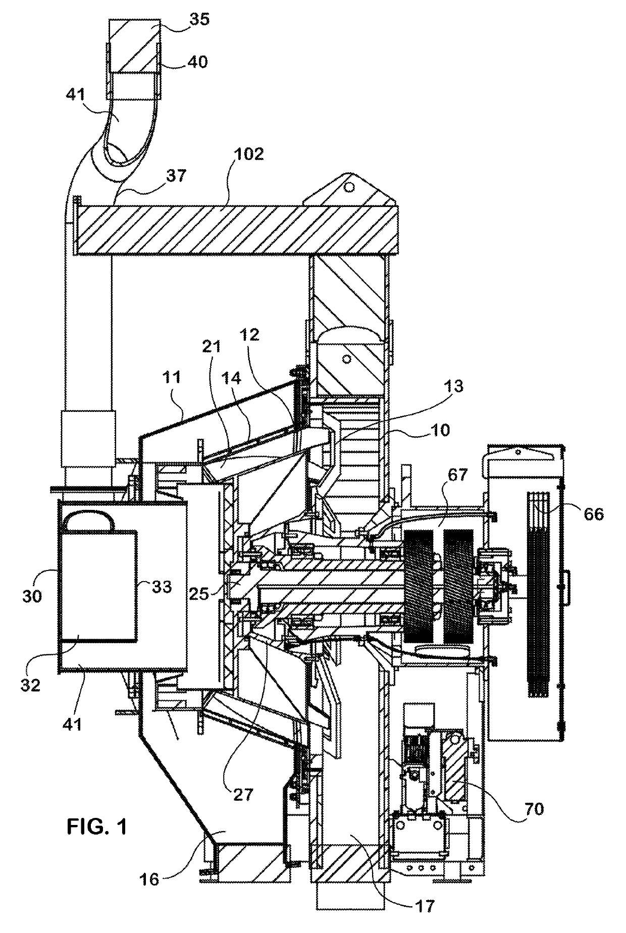
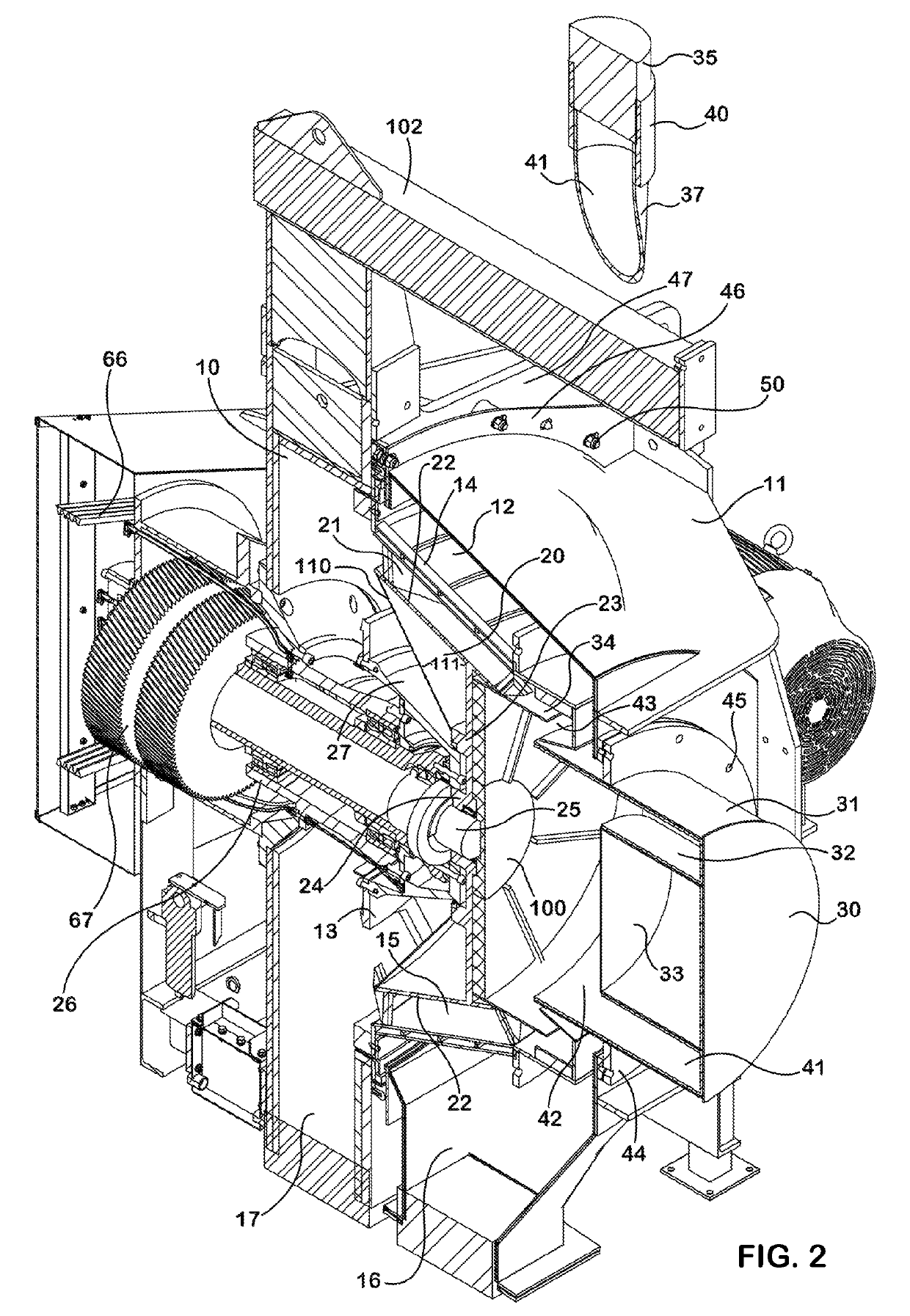
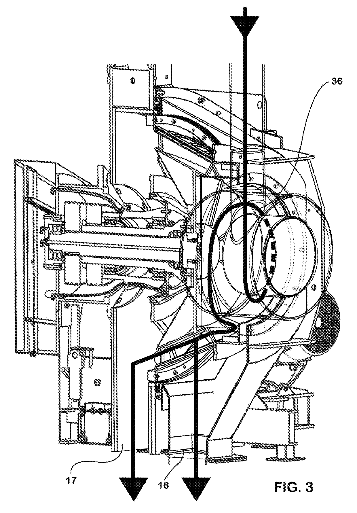
[0082]In the FIGS. 1 to 3 there is provided generally a centrifugal screening apparatus including an inner “dry side” housing portion 10 and an outer “wet side” housing portion 11. A screen assembly 12 is mounted for rotation in the wet side housing portion 11 and includes a base-of-spoke piece 13 and a frustoconical screen member 14 having a wedge-wire formed inner screening surface 15 and removably secured by its base to the base-of-spoke piece 13. The base of spoke piece 13 cooperates with the housing 10 to substantially divide the housing 10, the wet side housing portion 11 receiving filtrate passing through the screen member 14 to an effluent chamber 16 and the dry side housing portion 12 receiving product passing through the base-of-spoke piece 13 to a product delivery chamber 17. The filtrate or effluent chamber 16 is integrally formed with the outer wet side housing portion 11.

[0083]A scroll assembly 20 has a plurality of substantially helical scroll vanes 21 supported on a ...


PUM

PropertyMeasurementUnit
angleaaaaaaaaaa
rotationaaaaaaaaaa
wear resistantaaaaaaaaaa

Abstract

In a centrifugal screening apparatus wherein a housing (10, 11) mounts a screen assembly (12) and a scroll assembly (20) to be differentially rotated about the machine axis, there is provided an inlet assembly (30) having an inlet body (31) defining an annular inlet space (32) coaxial with and opening in to an open apical end of the screen assembly (12) and a material supply conduit (35) delivering material to be screened to the annular space (32) and being aligned in a tangent to the annular space to deliver material to the screen assembly (12) substantially in the direction of rotation of the screen assembly (12).

Description

CROSS-REFERENCE TO RELATED APPLICATIONS[0001]This application is a United States national phase of international patent application No. PCT / AU2015 / 050848, filed Dec. 27, 2015, which claims priority to Australian patent application No. 2015900107, filed Jan. 15, 2015, the entire disclosures of which are hereby incorporated herein by reference.TECHNICAL FIELD[0002]This disclosure relates in general to centrifugal screening apparatus and, in particular, to an improved fine coal centrifugal scroll screen machine.BACKGROUND OF THE DISCLOSURE[0003]Pulverized coal is washed by forming a water slurry and dewatering the slurry by passage through a fine coal centrifugal scroll screen machine. A typical machine is known as a vertical fine coal centrifugal scroll screen machine and includes a housing, a screen assembly mounted for rotation on a vertical axis in the housing and comprising a base-of-spoke piece supporting the lower, wider end of a frustoconical screen member, the base of spoke pi...

Claims


Application Information

Patent Timeline
Patent Type & Authority Patents(United States)
IPC IPC(8): B04B3/04B04B9/08B04B15/00B04B11/02B04B11/04B04B7/12B04B7/02G01N1/20B04B11/06
CPCB04B3/04B04B7/02B04B7/12B04B9/08B04B11/04B04B11/06B04B15/00G01N1/20B04B11/02G01N2001/2021
Inventor TRENCH, MICHAEL
Owner WEIR MINERALS AUSTRALIA LTD
Learn More