

Fluid control device and pump
a control device and fluid technology, applied in the direction of machines/engines, flexible member pumps, positive displacement liquid engines, etc., can solve the problems of reducing driving efficiency, difficult to achieve both reduced physical size and improved driving efficiency at the same time, etc., to achieve the effect of improving driving efficiency, increasing fluid volume, and reducing physical siz
- Summary
- Abstract
- Description
- Claims
- Application Information
AI Technical Summary
Benefits of technology
Problems solved by technology
Method used
Image

Examples
first embodiment
[0050]Hereinafter, a pump 1 according to a first embodiment of the present disclosure will be described with reference to an air pump that sucks gas as an example.
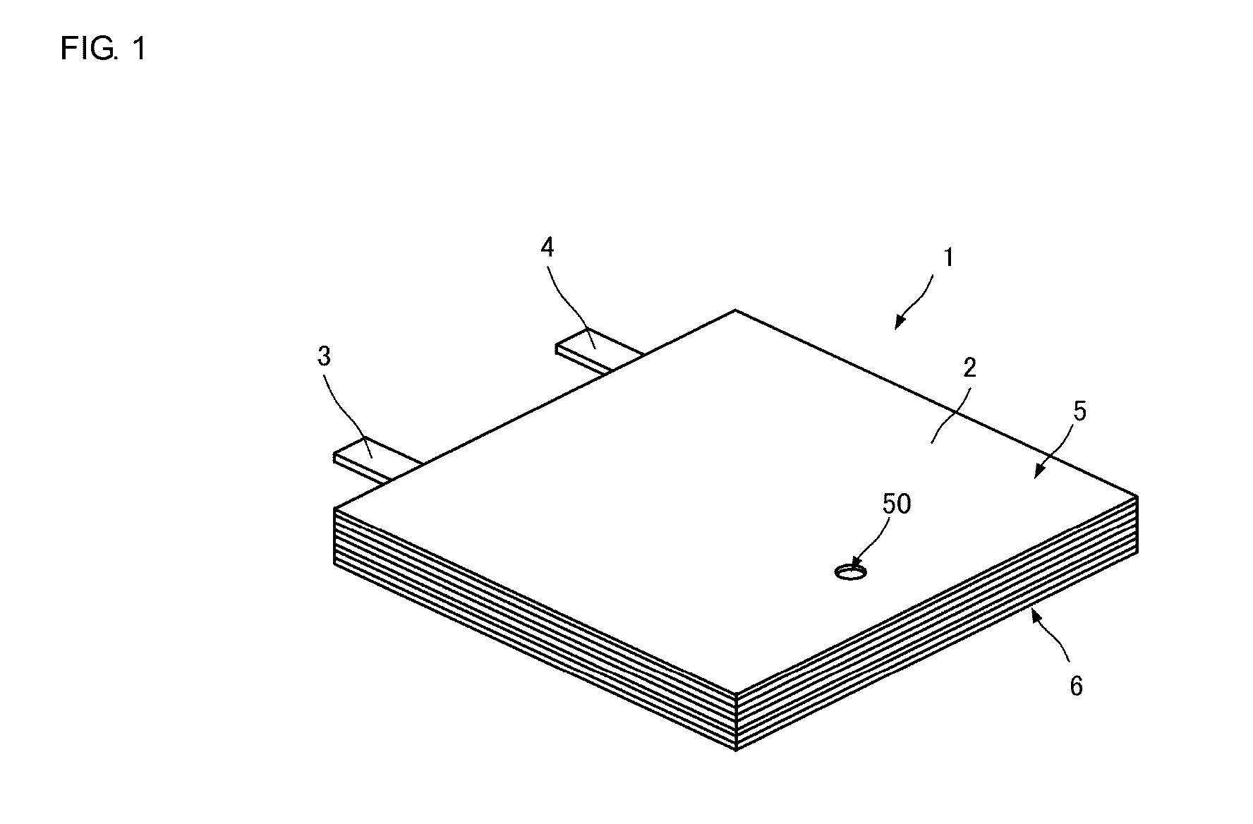
[0051]FIG. 1 is an external perspective view of the pump 1. As illustrated in FIG. 1, the pump 1 includes a housing 2, and external connection terminals 3 and 4. The external connection terminals 3 and 4 are each connected to an external power source, and applied with an alternating-current drive signal. The housing 2, which has a principal face (upper principal face) 5 and a principal face (lower principal face) 6, is a hexahedron with a small thickness between the principal faces 5 and 6. The housing 2 also has a channel hole 50 provided at the upper principal face 5, and channel holes 31, 32, 33, and 34 (see FIG. 2) provided at the lower principal face 6.
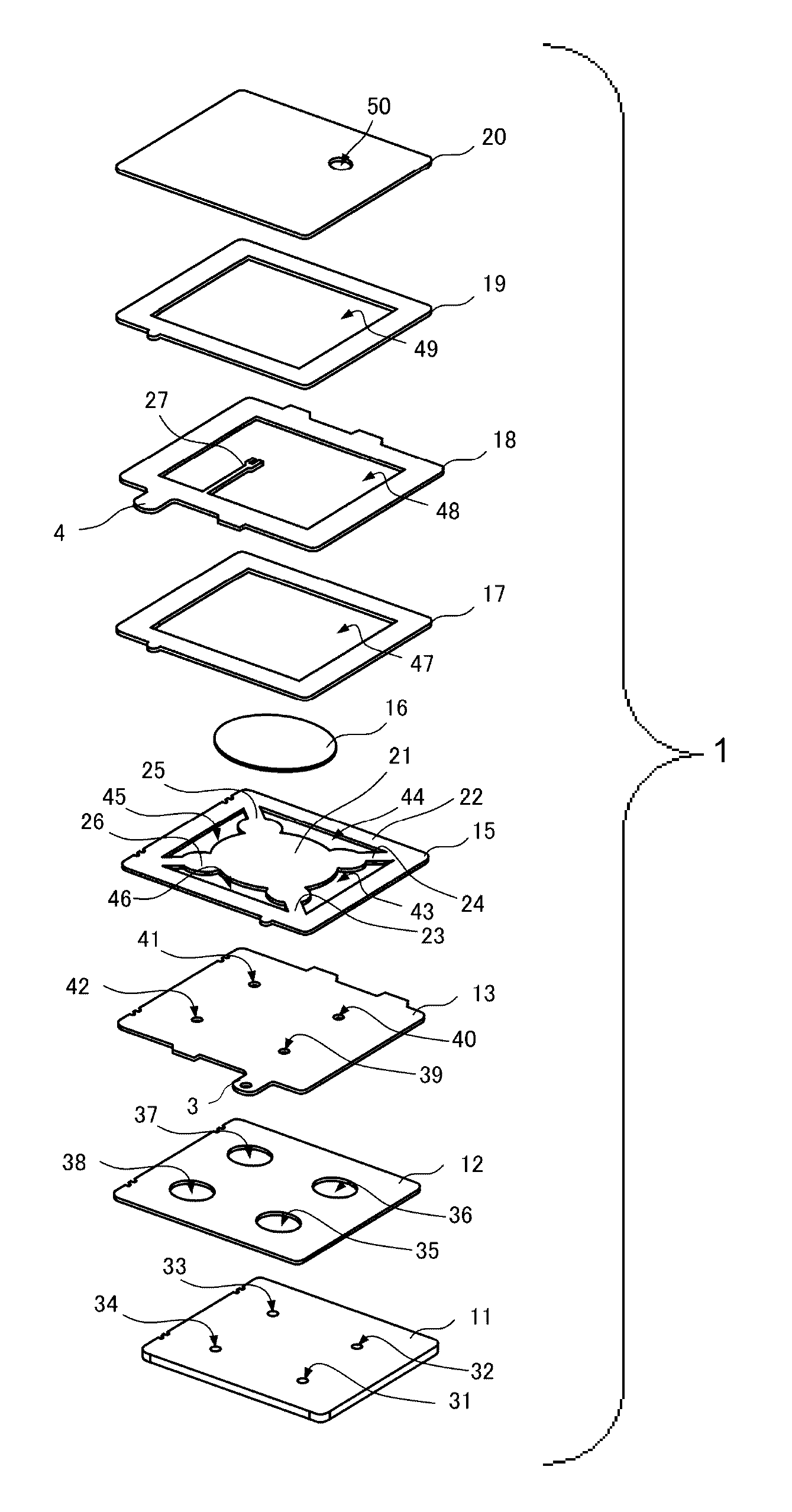
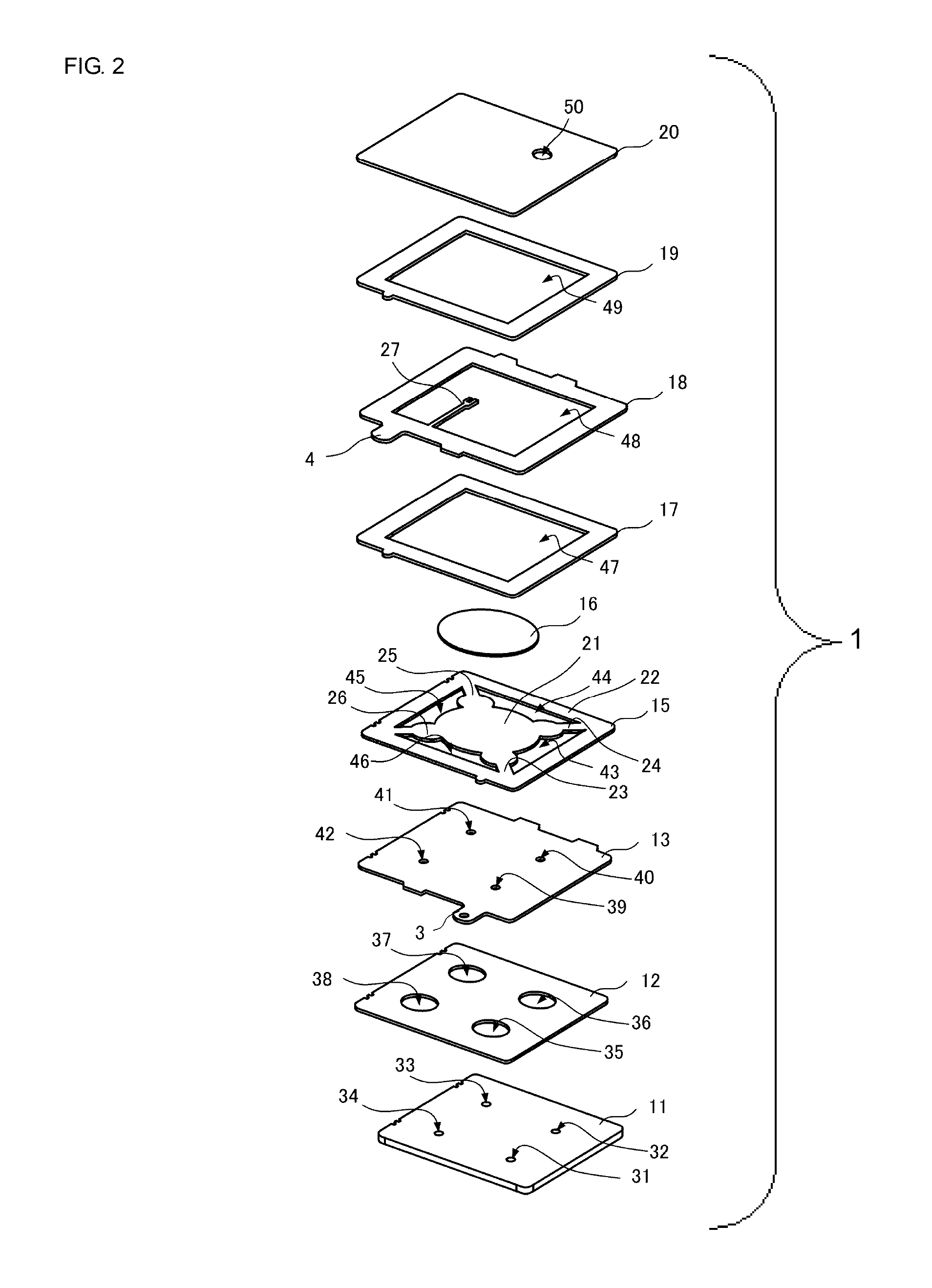
[0052]FIG. 2 is an exploded perspective view of the pump 1. As illustrated in FIG. 2, the pump 1 includes the following components stacked in the order stated below: a ...
second embodiment
[0087]Next, a pump 1A according to a second embodiment of the present disclosure will be described with reference to an air pump that sucks gas as an example.
[0088]FIG. 6 is an exploded perspective view of the pump 1A. The pump 1A includes the following components stacked in the order stated below: a cover plate 11A, a channel plate 12A, an opposed plate 13A, the adhesion layer 14 (not illustrated), the vibrating plate 15, the piezoelectric element 16, a metal plate 17A, the insulating plate 17, the power feeding plate 18, the spacer plate 19, and the lid plate 20. The adhesion layer 14 (not illustrated), the vibrating plate 15, the piezoelectric element 16, the insulating plate 17, the power feeding plate 18, the spacer plate 19, and the lid plate 20 are of substantially the same configuration as those in the first embodiment. The side wall surface of each of the vibrating plate 15, the insulating plate 17, the power feeding plate 18, and the spacer plate 19 that faces the pump cha...
third embodiment
[0103]Next, a pump 1B according to a third embodiment of the present disclosure will be described with reference to an air pump that sucks gas as an example.
[0104]FIG. 9 is an exploded perspective view of the pump 1B. The pump 1B includes the cover plate 11, the channel plate 12, the opposed plate 13, the adhesion layer 14 (not illustrated), the vibrating plate 15, the piezoelectric element 16, the insulating plate 17, the power feeding plate 18, the spacer plate 19, the lid plate 20, and a stacking plate 16B.
[0105]The stacking plate 16B is further stacked for the stack of the vibrating plate 15 and the piezoelectric element 16. In the third embodiment, the stacking plate 16B is stacked between the vibrating plate 15 and the piezoelectric element 16. The stacking plate 16B has substantially the same disc-like outer shape as that of the piezoelectric element 16, and has dimensions that are the same as or slightly larger than those of the piezoelectric element 16 in plan view.
[0106]As...
PUM
 Abstract
Description
Claims
Application Information