Touch Faucet

a faucet and touch technology, applied in the field of faucets, can solve the problems of high cost and complexity of conventional control valves for spraying faucets, inability to smoothly operate the faucet, and long operation travel, so as to save water supply

Inactive Publication Date: 2017-03-02
GLOBE UNION INDAL
View PDF26 Cites 17 Cited by
  • Summary
  • Abstract
  • Description
  • Claims
  • Application Information

AI Technical Summary

Benefits of technology

[0019]The touch faucet is capable of saving the water supply and adjusting water

Problems solved by technology

A conventional control valve for a spray head of a faucet is manufactured at high cost and is complicated.
In addition, one touch control valves are sold by many companies, such as 3M, wherein each one touch control valve is fixed on an outlet of the faucet and the water supply is started or stopped by manually touching an actuation element in the control valve, thus causing

Method used


Image

  • Touch Faucet
  • Touch Faucet
  • Touch Faucet

Examples


first embodiment

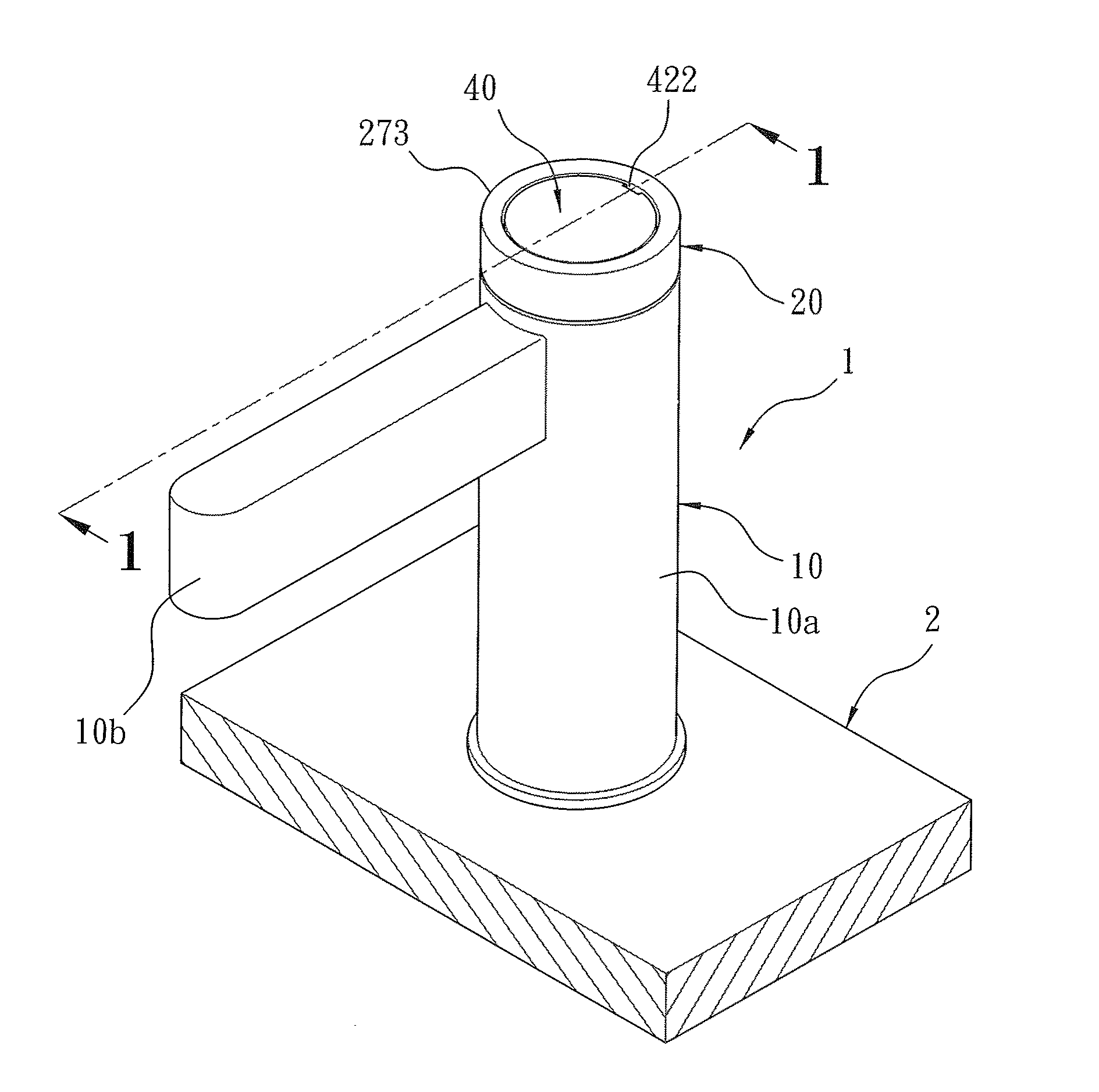
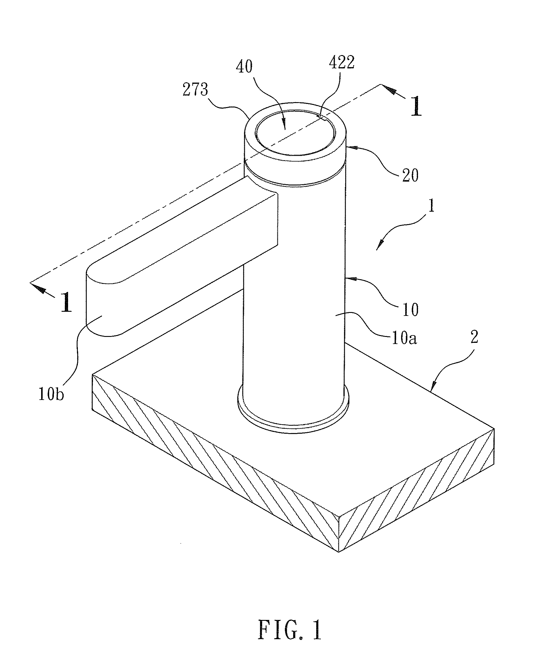
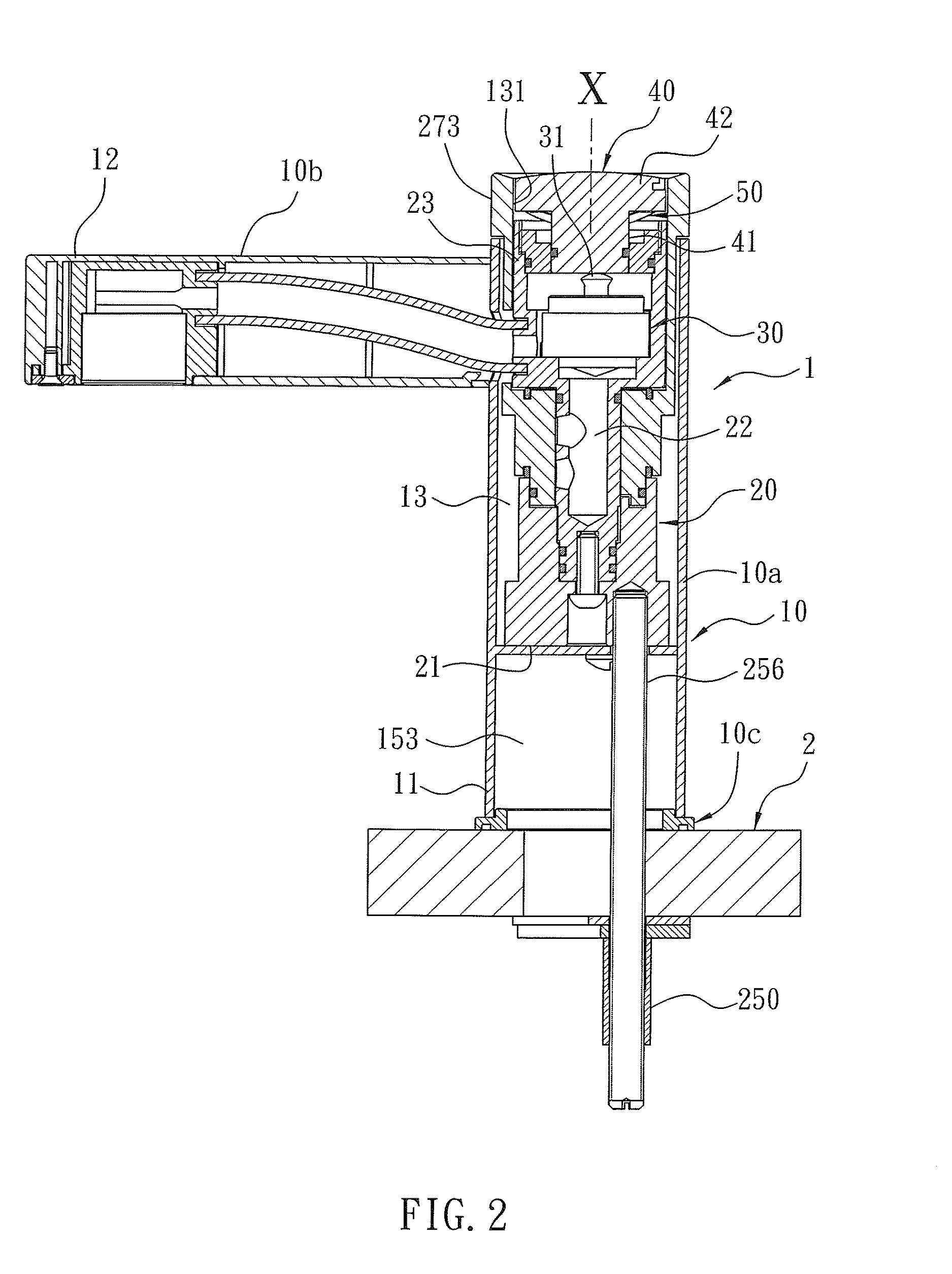
[0074]With reference to FIGS. 1-3, a touch faucet 1 according to the present invention is mounted on a basin or a fixing wall 2 in a bathroom and includes a body 10, a temperature control valve 20, a water control valve 30, and an actuation member 40.

[0075]Referring to FIGS. 4 and 5, the body 10 includes an inlet segment 11, an outlet segment 12, and a first cavity 13 defined between the inlet segment 11 and the outlet segment 12, wherein the first cavity 13 has a first hole 131 formed on a top thereof.

[0076]The temperature control valve 20 is housed in the first cavity 13 from the first hole 131 of the body 10, and the temperature control valve 20 includes a water inflow portion 21 configured to flow cold water and hot water, a mixing chamber 22 in which the cold water and the hot water are mixed together at a predetermined ratio so as to form a mixing water, and a water outflow portion 23 configured to flow the mix water, wherein the water outflow portion 23 is in communication wi...

second embodiment

[0118]Referring to FIGS. 40 to 46, the temperature control valve 202 further includes a valve seat 20e, an adjustment column 20a, a cover 20b, a definition loop 20c, and an adjusting ring 20d; wherein the adjustment column 20a, the cover 20b, the definition loop 20c, and the adjusting ring 20d are identical to those of the

[0119]The valve seat 20e is accommodated in the first cavity 13 of the cylinder 104 and includes a first conduit 290 configured to flow the cold water, a second conduit 291 configured to flow the hot water, a flowing channel 292 configured to flow a mixing water of the cold water and the hot water, and a housing trench 293. The first conduit 290 has a cold-water inlet 294 formed on a first end thereof so as to connect with a cold-water inflow pipe 61, and the second conduit 291 has a hot-water inlet 295 arranged on a first end thereof so as to connect with a hot-water inflow pipe 62. The first conduit 290 has a first opening 296 formed on a second end thereof in th...


PUM


Abstract

A touch faucet contains: a body, a temperature control valve, a water control valve, and an actuation member. The body includes an inlet segment, an outlet segment, and a first cavity which has a first hole. The temperature control valve is housed in the first cavity and includes a water inflow portion configured to flow cold water and hot water, a mixing chamber in which the cold water and the hot water are mixed to form a mixing water, and a water outflow portion configured to flow the mix water. The water control valve includes an operation post touched to turn on the water control valve, such that the mixing water flows into the water outflow portion from the mixing chamber, and the actuation member partially exposes outside the body so as to be operated by a user to drive the operation post to move.

Description

FIELD OF THE INVENTION[0001]The present invention relates to a faucet, and more particularly to a touch faucet.BACKGROUND OF THE INVENTION[0002]A conventional control valve for a spray head of a faucet is manufactured at high cost and is complicated. Accordingly, improved touch control valves were disclosed in TW Patent Nos. M432670, I228578, I369459, M452280 and M382408, respectively. The improved touch control valves are an automatic valve or a manual valve, wherein when the touch control valves are the manual valve, water supply is stopped by touching an actuation element, after starting the water supply. When the touch control valves are the automatic valve, the water supply is stopped automatically by way of water pressure change after a period of using time.[0003]In addition, one touch control valves are sold by many companies, such as 3M, wherein each one touch control valve is fixed on an outlet of the faucet and the water supply is started or stopped by manually touching an...

Claims


Application Information

Patent Timeline
IPC IPC(8): F16K21/06E03C1/04
CPCF16K21/06E03C2001/0415E03C2001/026E03C1/04F16K11/074F16K11/076F16K19/006
Inventor CHIU, HUILINGYUAN, CHIAHUALIN, YIPING
Owner GLOBE UNION INDAL
Why Eureka
Try Eureka