Multi-element sensor array calibration method

a sensor array and array technology, applied in the field of multi-element sensor array calibration methods, can solve the problems of reducing or increasing impedance, magnitude or phase of current, method is relatively slow, arrays generally have a lower sensitivity and resolution compared to rastered single sensors, and achieve reliable rejection thresholds.

Active Publication Date: 2017-03-02
ROLLS ROYCE PLC
View PDF2 Cites 4 Cited by
  • Summary
  • Abstract
  • Description
  • Claims
  • Application Information

AI Technical Summary

Benefits of technology

[0013]It has been found by the inventors that a rejection threshold based on the root mean squared average (RMS) of an array spatial response function provides a more reliable rejection threshold than the prior art method. It has also been found that an approximation for the RMS value of the array spatial response function can be found from a single pass of the array by providing at least a pair of calibrated defects arranged such that, when one calibrated defect is located at the peak of the array response function, the other is at the minimum. Consequently, the variations in sensor signals from sensor elements at different positions in the array is cancelled out, such that the RMS average of the array function as a whole can be calculated using signals generated by these calibrated defects.

Problems solved by technology

For example, small defects at or near the surface will result in a reduced or increased impedance, magnitude or phase of the current relative to other areas.
However, such a method is relatively slow.
However, such arrays generally have a lower sensitivity and a lower resolution compared to rastered single sensors, which is limited by the spacing d2 in the example shown in FIG. 2.
However, it has been found that such calibration methods may result in some defects going undetected.
Consequently, such calibration methods are time consuming.
Similar problems also occur in other multi-element sensor arrays.

Method used


Image

  • Multi-element sensor array calibration method
  • Multi-element sensor array calibration method
  • Multi-element sensor array calibration method

Examples


Embodiment Construction

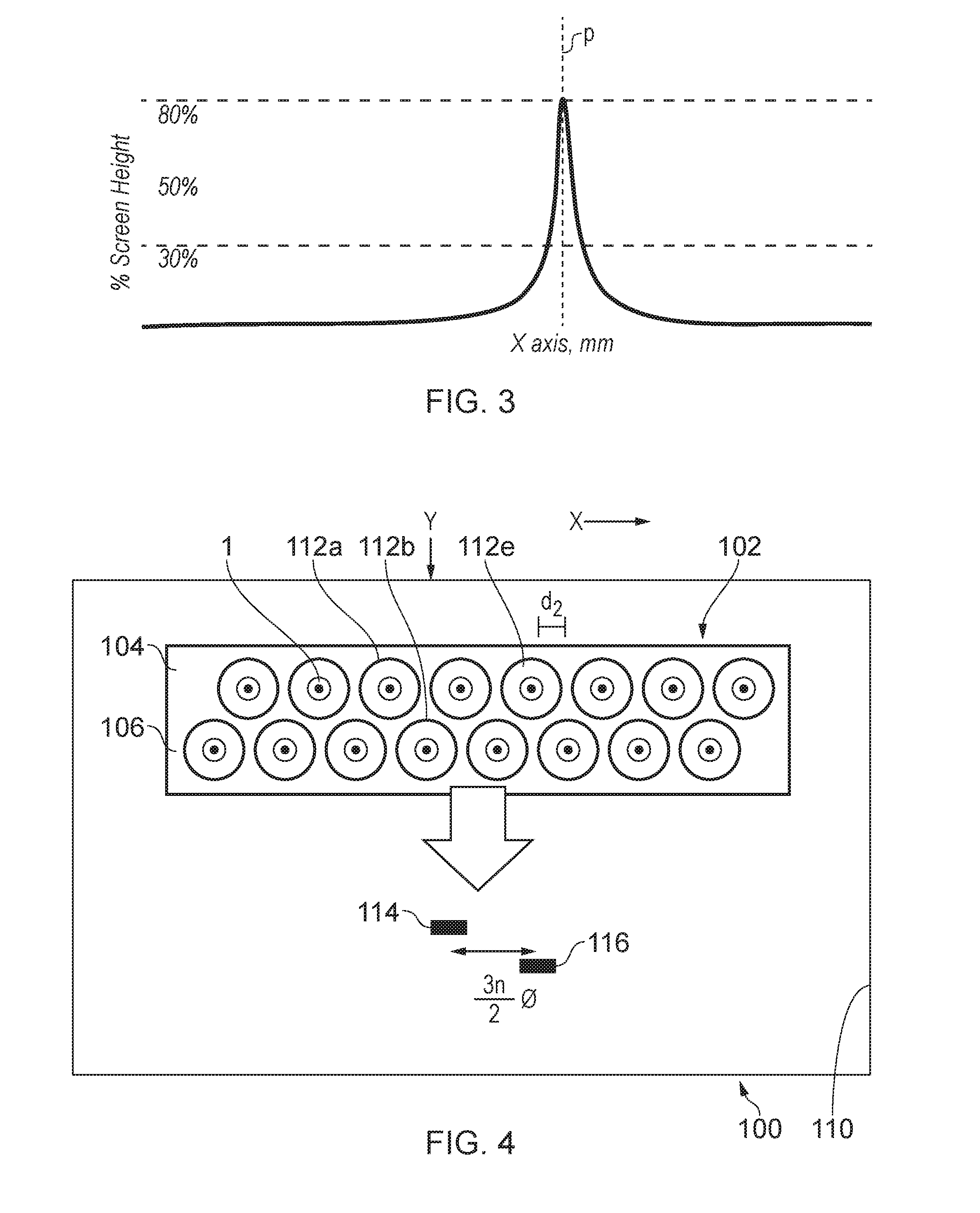
[0034]FIG. 4 shows an eddy current array inspection device calibration apparatus 100. The apparatus 100 comprises an eddy current array inspection device 102 and a calibration block 110.

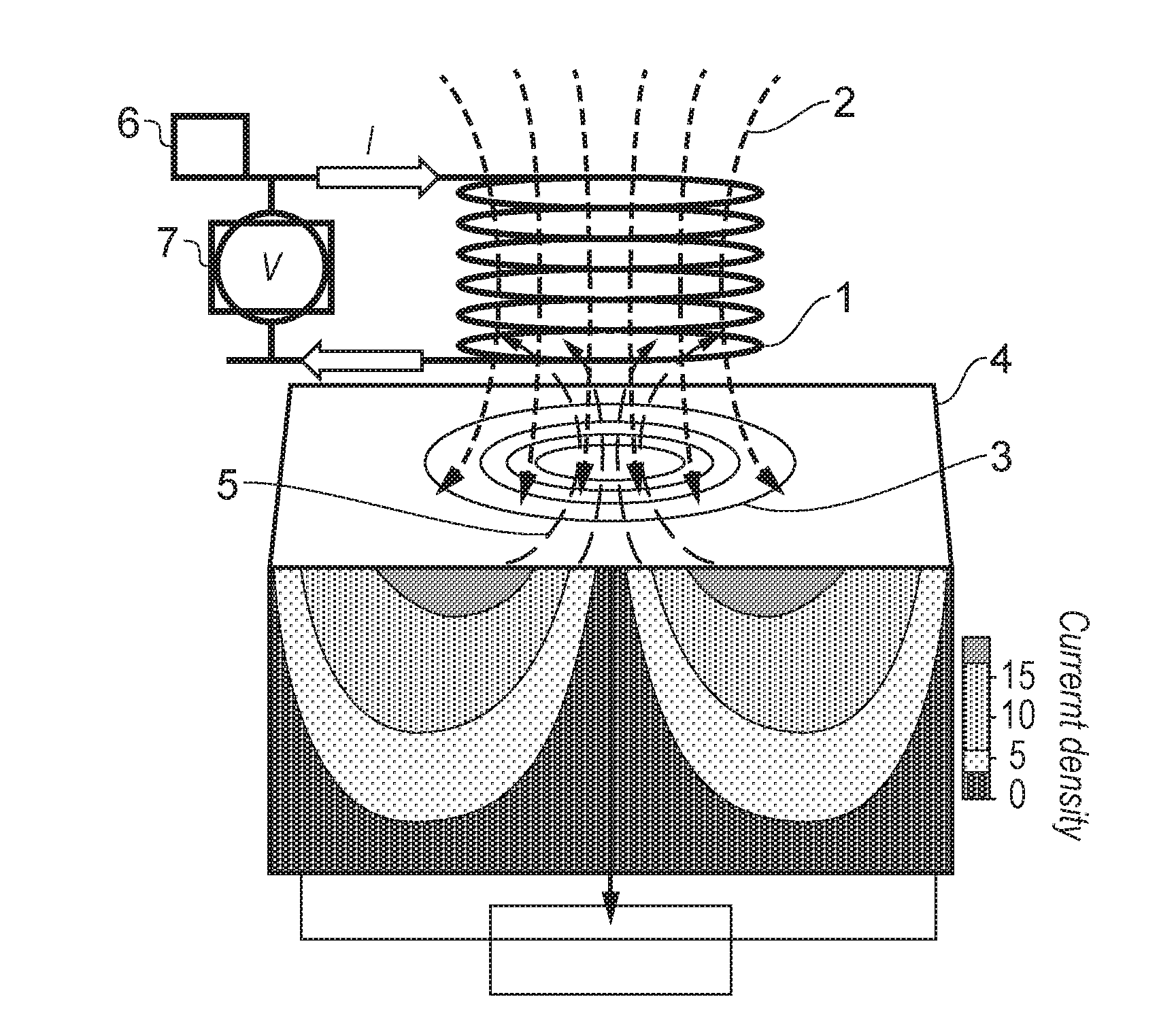
[0035]The inspection device 102 comprises a plurality of sensor elements 112. Each sensor element 112 comprises an electromagnetic coil 1 (shown in further detail in FIG. 1), which is connected to a power source 7 and an electrical current sensor 6, which detects at least one of the impedance (Z), magnitude (|Z|) and phase (φ) of the current I flowing through the coil 1, to thereby detect near surface defects in an electrically conductive article comprising, for instance, a metal or a carbon fibre composite.

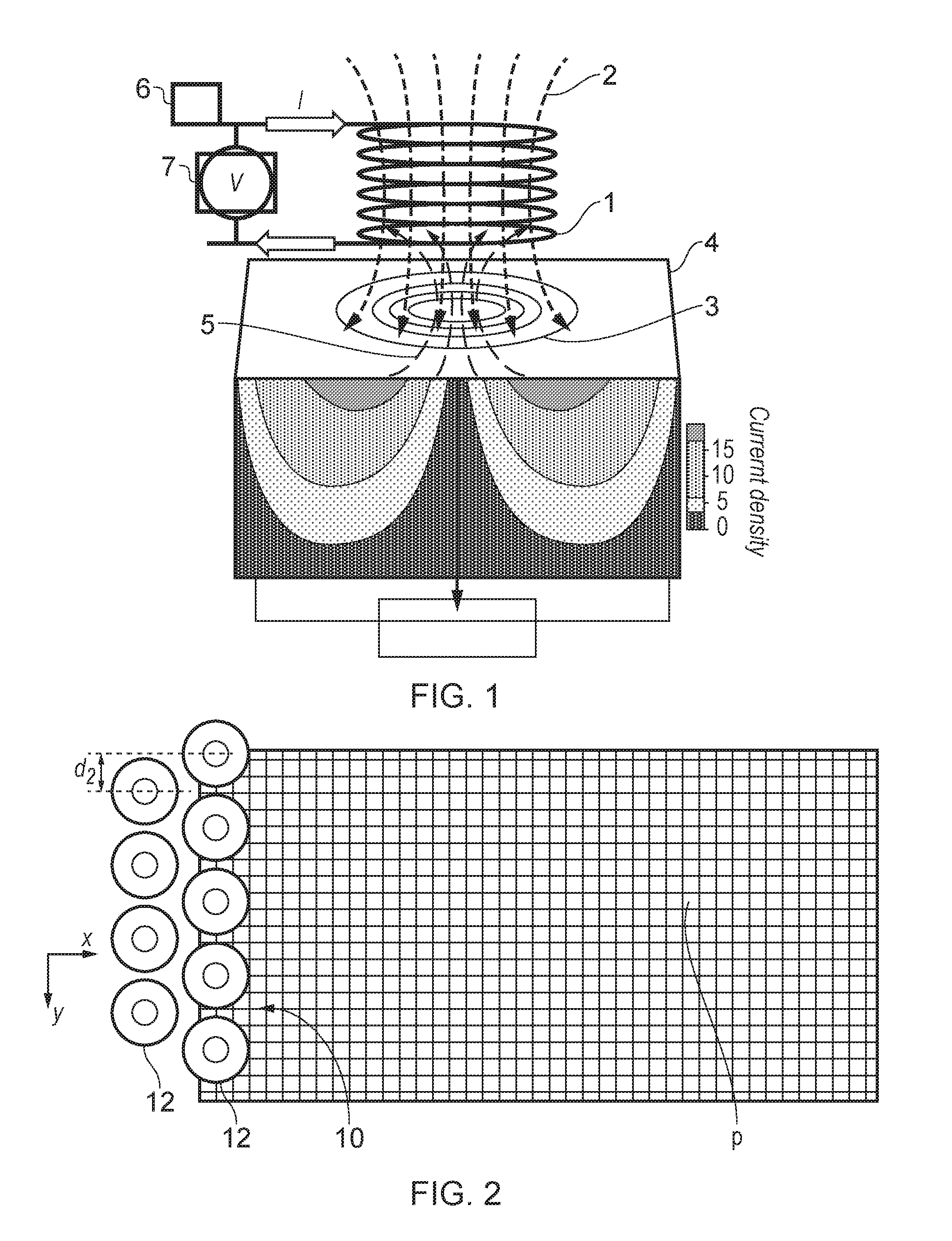
[0036]The coils 1 of the sensors 112 of the inspection device 102 are spaced apart in rows 104, 106 extending in a direction X to define an array. The array further defines a direction Y normal to the direction X, parallel to the surface of the calibration block in use. Each row 104, 106 is stagge...


PUM


Abstract

A method of calibrating a sensor array having elements spaced from one another in a first direction, the array defining an array spatial response function, includes: providing a test workpiece having at least first and second calibrated defects spaced apart in the first direction by a characteristic distance such that when the first calibrated surface defect is located at a position corresponding to an array response function maximum, the second calibrated surface defect is located at a position corresponding to an array response function minimum; passing the array across the first and second calibrated surface defects in a direction normal to the first direction and determining a peak sensor signal from at least two of the elements in the array to determine an array spatial response function root mean squared average; and setting a rejection threshold as a predetermined proportion of the array spatial response function root mean squared average.

Description

FIELD OF THE INVENTION[0001]The present invention relates to a method of calibrating a multi-element sensor array such as an eddy current array (ECA).BACKGROUND TO THE INVENTION[0002]FIG. 1 illustrates the working principle of an eddy current inspection device for inspecting an electrically conductive workpiece 4. The device operates by flowing a primary electrical current through a sensor comprising a coil of wire 1 to induce a primary magnetic field indicated by 2. The primary magnetic field 2 in turn induces a secondary electrical field 3 in an adjacent conductive (e.g. metallic) workpiece 4 to be inspected. The secondary electrical field 3 in turn induces a secondary magnetic field 5, which interacts with the primary electrical current flowing through the coil 1. The change in electrical current in the coil 1 can be detected by measuring one or more of the impedance (Z), magnitude (|Z|) and phase (φ) of the current I and / or voltage V flowing through the coil 1, to thereby deduce...

Claims


Application Information

Patent Timeline
Patent Type & Authority Applications(United States)
IPC IPC(8): G01R35/00
CPCG01R35/005G01N27/9086G01D18/008
Inventor HUGHES, ROBERT R.LANE, CHRISTOPHER J. L.
Owner ROLLS ROYCE PLC
Why Eureka
Try Eureka