Eureka AIR delivers breakthrough ideas for toughest innovation challenges, trusted by R&D personnel around the world.

Fixing device

Active Publication Date: 2017-03-02
CANON KK
View PDF3 Cites 10 Cited by
  • Summary
  • Abstract
  • Description
  • Claims
  • Application Information

AI Technical Summary

Benefits of technology

The present invention provides a fixing device for fixing an image on a recording material. The device includes a rotatable heating member with a base layer, electroconductive layers, and heat generating resistors. A temperature detecting member is used to detect the temperature of the heating member. An electrode member is used to supply electric power to the heat generating resistors. The heat generating resistors are arranged helically around the base layer and are disposed with intervals. The device also includes a temperature detecting region that overlaps with the heat generating resistors. The technical effect of this invention is to provide a more efficient and precise heating mechanism for fixing images on recording materials.

Problems solved by technology

However, strength of the insulating layers including the elastic layer and the parting layer is not sufficient, and therefore, there is a possibility that the insulating layers are damaged by friction (sliding) with a foreign matter which enters the fixing device from an outside or with a recording material and then the damage has the influence on the heat generating resistor layer.
Further, due to jam clearance by a user or the like, there is a possibility that the heat generating resistor layer is damaged with tweezers or a cutter.
In such a case, a current density locally increases at a periphery of an end portion of the damaged portion, so that there is a possibility that abnormal heat generation occurs at the portion.
However, when the crack C generates in the heat generating resistor layer, traveling (movement) of the currents I2 and I3 is blocked, so that the currents I2 and I3 flow along peripheries of end portions of the crack C. Therefore, in each of regions A and B at the peripheries of the end portions, the current concentrates and thus the current density increases, so that abnormal heat generation locally occurs in the portion (region A, region B).
At the portion where the abnormal heat generation occurs, a temperature remarkably increases compared with a normal portion, and therefore, the fixing film is thermally damaged and an image defect is caused in some cases.
However, in the constitution shown in FIG. 19, a new problem such that it becomes difficult to detect a temperature in a rotation stop state during the generation of the crack generates.
This is because in the case where the heat generating resistor is interrupted (broken) by the crack along the circumferential direction, heat does not generate in an entire longitudinal region in which the broken heat generating resistor is formed, and in this region, toner detection by a temperature detecting element provided in the longitudinal region cannot be made.
On the other hand, at a portion where the crack does not generate, toner increases and therefore abnormal high temperature in the rotation stop state cannot be immediately detected.

Method used


Image

  • Fixing device
  • Fixing device
  • Fixing device

Examples


first embodiment

Fixing Device

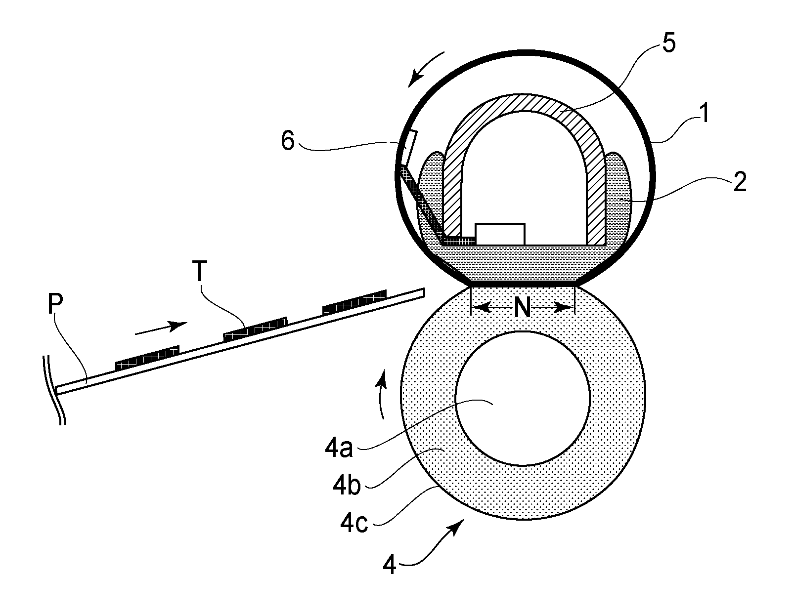
[0033]A fixing device using a rotatable heating member according to First Embodiment of the present invention will be described using FIG. 5. In FIG. 5, (a) is a schematic sectional view of the fixing device at a longitudinal central portion, and (b) is a schematic view of the fixing device as seen in a recording material feeding direction crossing the longitudinal direction.

[0034]The fixing device heats and fixes, at a nip (fixing nip), a toner image formed at an image forming portion by an image forming method of a general electrophotographic type. From a left-hand side of (a) of FIG. 5, a recording material P carrying thereon a toner image T is fed by an unshown feeding means and passed through the fixing device, so that the toner image T is heated and fixed on the recording material P.

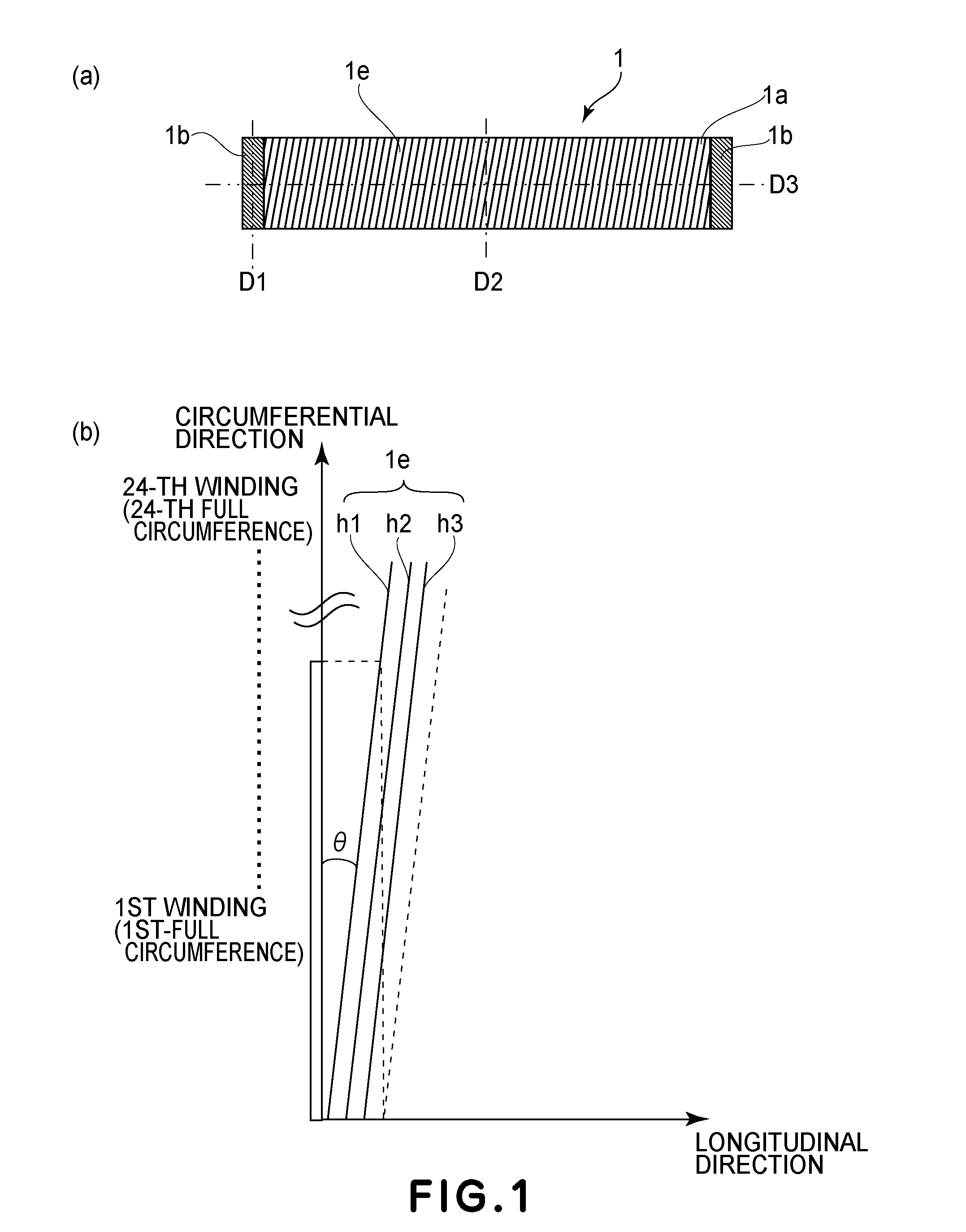
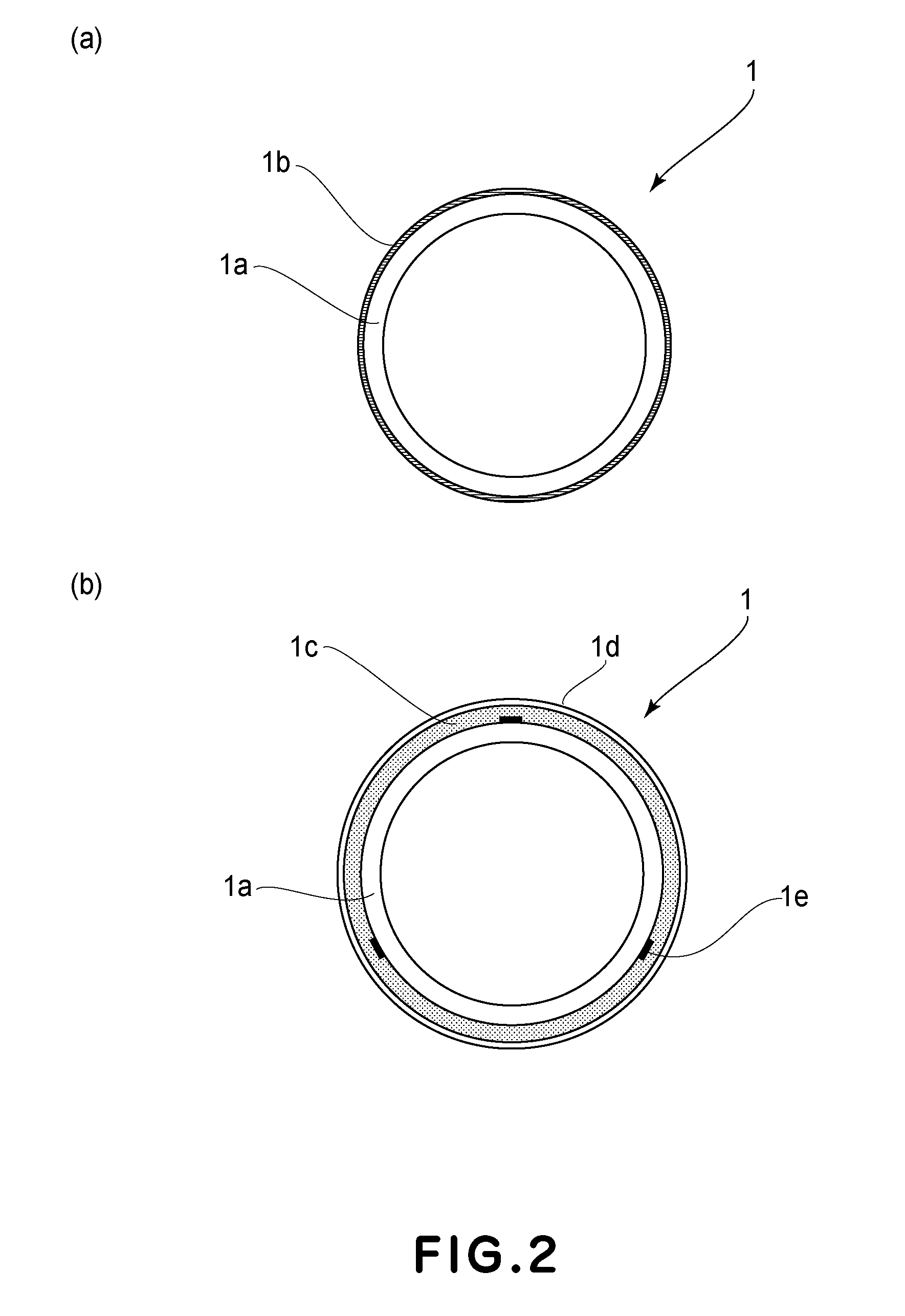
[0035]The fixing device in this embodiment is constituted by a cylindrical flexible fixing film 1 as a rotatable heating member, a film guide 2 for holding the fixing film 1, and a pre...

second embodiment

[0067]In the following, Second Embodiment of the present invention will be described using FIGS. 10-15. In this embodiment, as the rotatable heating member, the fixing film 1 was used, but in this embodiment, as the rotatable heating member, a fixing roller is used.

(Fixing Device)

[0068]In FIG. 13, (a) is a schematic sectional view of a principal part of a fixing device in this embodiment, and (b) is a schematic front view of the fixing device.

[0069]The fixing device in this embodiment is constituted by a fixing roller 19 as a rotatable heating member and a pressing roller 4 as a pressing member for forming the fixing nip (nip) in cooperation with the fixing roller 10.

[0070]The fixing roller 10 and the pressing roller 4 are pressed by an unshown pressing means, and a predetermined-width fixing nip N uniform with respect to the longitudinal direction of the pressing roller 4 is formed. Further, outside a surface of the fixing roller 10, a non-contact temperature detecting element 8 is...

third embodiment

[0092]In this embodiment, in the fixing device of First Embodiment, the number of heat generating resistors formed in the helical shape on the fixing film is increased to 6 as in Second Embodiment, and as the temperature detecting element, two thermistors are spaced in the longitudinal direction. Other constitutions are similar to those in First Embodiment, and therefore will be omitted from description.

[0093]In a constitution including the plurality of heat generating resistors, in the case where the resistance between the electroconductive layers at the longitudinal end portions is the same, an amount of a current per (one) heat generating resistor can be decreased with an increasing number of the heat generating resistors. For this reason, an abnormal heat generation suppressing effect in the case where a crack such that the heat generating resistors are partly broken generated becomes large. That is, an abnormal heat generation amount is smaller in this embodiment in which the 7...


PUM


Abstract

A fixing device includes a heating member including a base layer, first and second electroconductive layers and a plurality of heat generating resistors provided on the base layer and having a volume resistivity smaller than a volume resistivity of the base layer; a temperature detecting member; and an electrode member. The heat generating resistors are provided helically around the base layer so that a helical axis thereof extends along the longitudinal direction of the rotatable member, and are disposed with intervals. One end and the other end of each of the heat generating resistors are electrically connected with the first and the second electroconductive layers, respectively. A temperature detecting region of the rotatable member by the temperature detecting member overlaps with the heat generating resistors.

Description

FIELD OF THE INVENTION AND RELATED ART[0001]The present invention relates to a fixing device using a cylindrical rotatable member (rotatable heating member) and is suitable for the fixing device for use with an image forming apparatus such as a printer or a copying machine.[0002]As the fixing device for the image forming apparatus such as the printer or the copying machine, a fixing device in which electric power is supplied to a rotatable heating member such as a roller including an electroconductive layer to cause Joule heating (heat generation) and thus high-speed rising and energy saving are realized is used. Specifically, Japanese Laid-Open Patent Application 2013-97315 discloses a fixing member including a heat generating resistor layer in which a carbon filler is dispersed in a heat-resistant resin material and including insulating elastic layer and parting layer which are coated on the heat generating resistor layer. In this fixing device, heat is generated by directly suppl...

Claims


Application Information

Patent Timeline
IPC IPC(8): G03G15/20
CPCG03G15/2039G03G15/2053
Inventor NARAHARA, TAKASHISHINJI, TAKESHIIMAIZUMI, TORUDODA, KAZUHIROWAKATSU, KOHEI
Owner CANON KK
Why Eureka
Eureka Blog
Learn More