Image measuring apparatus and non-temporary recording medium on which control program of same apparatus is recorded

a technology of image measuring apparatus and control program, which is applied in the field of image measuring apparatus, can solve problems such as the inability to accurately acquire measurement valu

Active Publication Date: 2017-03-02
MITUTOYO CORP
View PDF7 Cites 3 Cited by
  • Summary
  • Abstract
  • Description
  • Claims
  • Application Information

AI Technical Summary

Benefits of technology

[0005]The present invention was made in view of such a point, and has an object of providing an image measuring apparatus capable of appropriately extracting a portion representing a measurement target from within an image and performing dimensional measurement or form measurement, and of providing a non-temporary recording medium on which a control program of the image measuring apparatus is recorded.

Problems solved by technology

For example, sometimes, when the image measuring apparatus was employed to perform dimensional measurement or form measurement of the workpiece, a portion representing a measurement target could not be appropriately extracted from within the image, and a measurement value could not be accurately acquired.

Method used


Image

  • Image measuring apparatus and non-temporary recording medium on which control program of same apparatus is recorded
  • Image measuring apparatus and non-temporary recording medium on which control program of same apparatus is recorded
  • Image measuring apparatus and non-temporary recording medium on which control program of same apparatus is recorded

Examples


first embodiment

[0034]Next, a first embodiment of the present invention will be described in detail with reference to the drawings.

[0035]First, a schematic configuration of an image measuring apparatus according to the present embodiment will be described with reference to FIG. 1.

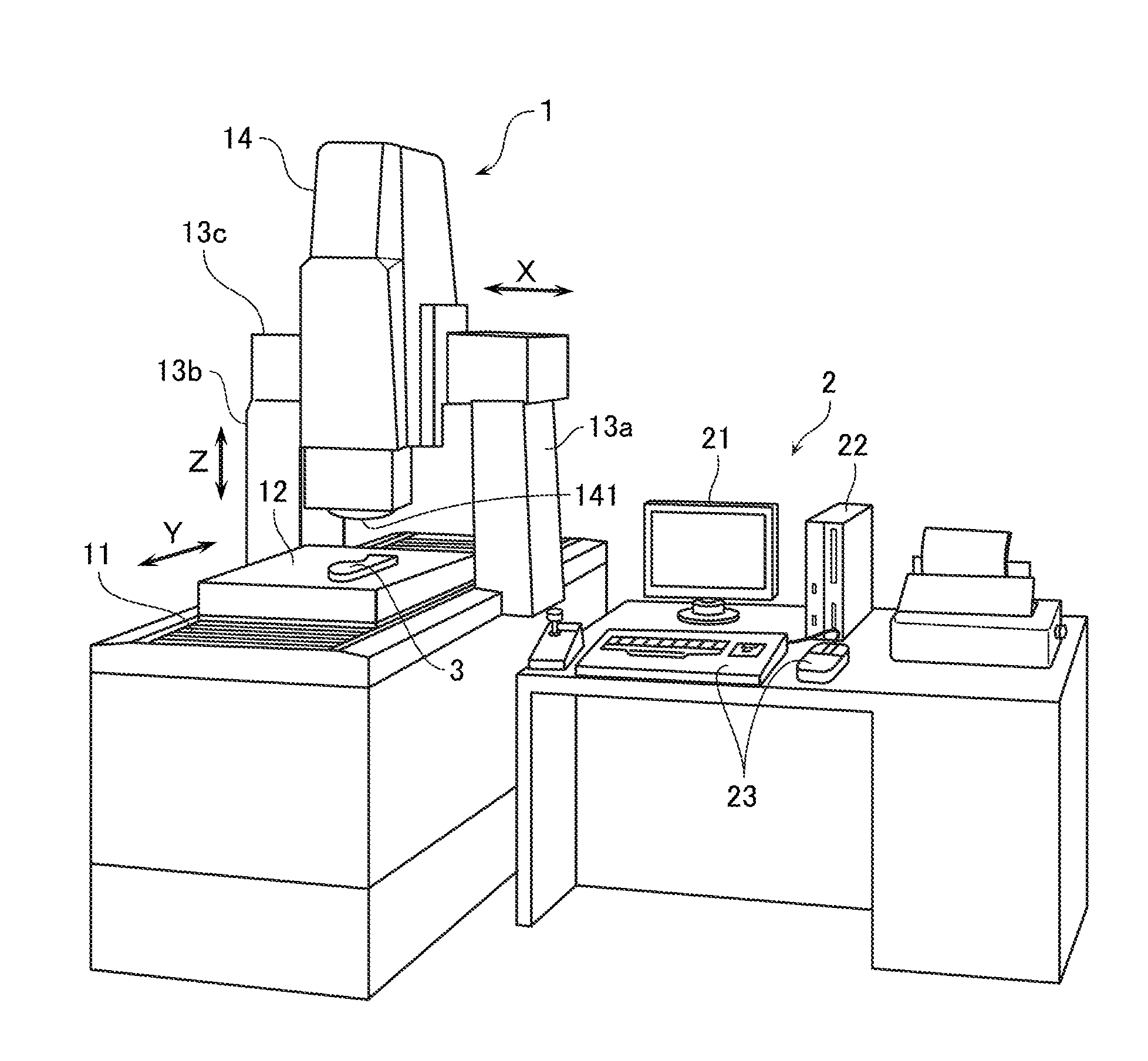
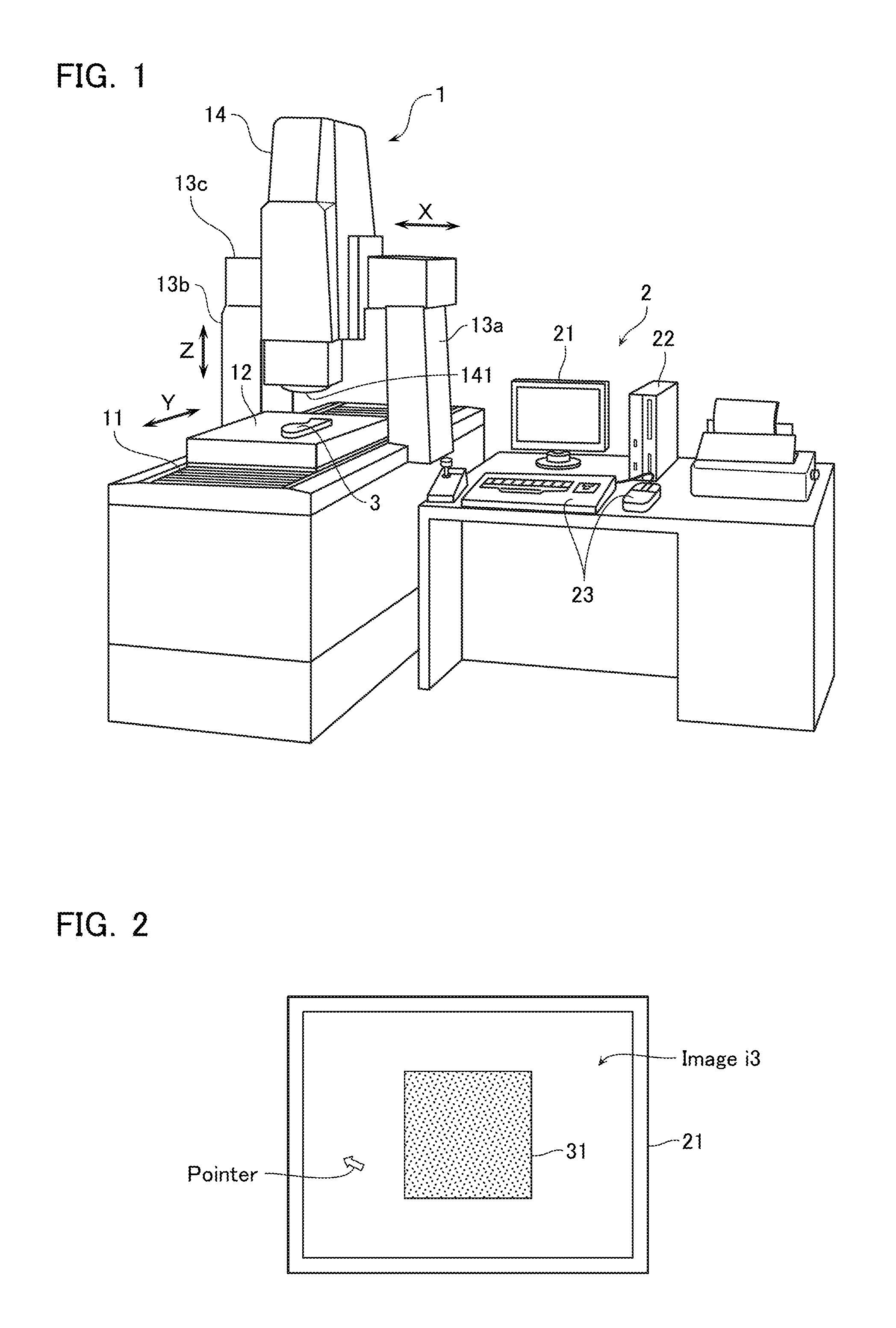
[0036]As shown in FIG. 1, the image measuring apparatus according to the present embodiment comprises: an image measuring instrument 1 that comprises mutually orthogonal X, Y, and Z axes, and has a camera 141 mounted as an imaging device that images a workpiece 3, at an extremity of this Z axis; and a computer (hereafter, called “PC”) 2 connected to this image measuring instrument 1.

[0037]The image measuring instrument 1 is configured as follows. That is, a workstage 12 is mounted on a sample moving means 11, so that an upper surface of the workstage 12 acting as a base plane coincides with a horizontal plane, and an X axis guide 13c is supported by upper ends of arm support bodies 13a and 13b erected from edges on both si...

second embodiment

[0066]Next, an image measuring apparatus according to a second embodiment of the present invention will be described with reference to FIG. 20. Note that in the description below, portions similar to those of the first embodiment will be assigned with identical reference symbols to those assigned in the first embodiment, and descriptions thereof will be omitted.

[0067]The image measuring apparatus according to the present embodiment is basically configured similarly to that of the first embodiment, but differs from that of the first embodiment in the following point. That is, in the present embodiment, after the likes of the centroid or contour line of the measurement target have been calculated based on the second point group in step S104, edge detection is further performed. The edge detection can be performed in a variety of modes, but in the example shown in FIG. 20, an edge detection tool t is set in the measurement target 31 based on the calculated centroid or contour line, and...

third embodiment

[0074]Next, an image measuring apparatus according to a third embodiment of the present invention will be described with reference to FIGS. 21 to 23. Note that in the description below, portions similar to those of the first embodiment will be assigned with identical reference symbols to those assigned in the first embodiment, and descriptions thereof will be omitted.

[0075]The image measuring apparatus according to the present embodiment is basically configured similarly to that of the first embodiment, but differs from that of the first embodiment in the following point. That is, in the present embodiment, as shown in FIG. 21, the binarized image has the plurality of first points set therein so as to surround a measurement target 33, and, as shown in FIG. 22, these plurality of first points are moved to acquire the second point group aligned along the contour of the measurement target 33. Moreover, as shown in FIG. 23, the outside of the contour of the measurement target 33 is fill...


PUM


Abstract

An image measuring apparatus according to an embodiment of the present invention comprises: an imaging device that images a workpiece to acquire an image of this workpiece; and a processing device that performs measurement of the workpiece based on this image and outputs a measurement result. Moreover, the processing device sets a region in the image, sets a plurality of first points along a contour line of this region, sequentially moves these plurality of first points so that the plurality of first points approximate to the contour line included in the image, acquires the moved plurality of first points as a plurality of second points, and calculates the measurement result based on these plurality of second points.

Description

CROSS-REFERENCE TO RELATED APPLICATIONS[0001]This application is based upon and claims the benefit of Japanese Patent Application No. 2015-170614, filed on Aug. 31, 2015, the entire contents of which are incorporated herein by reference.FIELD[0002]The present invention relates to an image measuring apparatus that measures a workpiece by imaging the workpiece, and also relates to a non-temporary recording medium on which a control program of the image measuring apparatus is recorded.BACKGROUNDDescription of the Related Art[0003]As a measuring apparatus for performing dimensional measurement or form measurement of a workpiece, that is, an object-to-be-measured, for example, an image measuring apparatus is known. The image measuring apparatus comprises: an imaging device that images the workpiece to acquire an image; and a processing device that performs image processing on this image and performs dimensional measurement or form measurement of the workpiece (JP 2001-241941 A).[0004]For...

Claims


Application Information

Patent Timeline
Patent Type & Authority Applications(United States)
IPC IPC(8): G06T7/00G06K9/46
CPCG06T7/0012G06T7/0081G06K9/4671G06T2207/30164G06K9/4604G06K2009/4666G06T2207/20112G06T7/0085G01B11/00G06T7/60G06T2207/20116G06V10/755
Inventor KURIHARA, MASAKI
Owner MITUTOYO CORP
Why Eureka
Try Eureka