Control device and control method for robot and the robot

a control device and robot technology, applied in the direction of programmed control, manipulators, instruments, etc., can solve the problems of deterioration of the accuracy of vibration caused by vibration, the inability to suppress vibration and motion strain, and the inability to move the robot arm

Active Publication Date: 2015-08-04
SEIKO EPSON CORP
View PDF26 Cites 2 Cited by
  • Summary
  • Abstract
  • Description
  • Claims
  • Application Information

AI Technical Summary

Benefits of technology

[0008]With the control device for the robot according to this application example, the third arm speed in the damping position is calculated on the basis of information concerning the first arm speed obtained from the inertia sensor and information concerning the second arm speed obtained from the angle sensor. The correction speed for each driving unit that drives the links present between the robot main body and the damping position is calculated on the basis of the calculated third arm speed. By controlling the respective driving units on the basis of the correction speed for each of the driving units, it is possible to suppress vibration that occurs in the damping position.
[0030]In this application example, since the control device further includes the filter for removing the low frequency component of the third arm speed, it is possible to more appropriately extract a vibration component through the evaluation of the difference between the first arm speed and the second arm speed. Specifically, it is possible to reduce the influence of an incorrect correction for suppressing the original motion of the robot arm, an offset error of the inertia sensor, and the like by removing the low frequency component of the third arm speed.

Problems solved by technology

However, the control method (i.e., the damping method) described in JP-A-2011-136395 has a problem in that the vibration that occurs during the motion of the robot cannot be suppressed.
Specifically, since the method is based on the premise that the timing for acceleration detection is the time when the motion of the robot stops, for example, the vibration and motion strain that occurs during movement of a robot arm cannot be eliminated.
Thus, when an operator causes the robot to perform a function such as painting or welding while moving the robot, the deterioration of the accuracy thereof due to the vibration cannot be suppressed.

Method used


Image

  • Control device and control method for robot and the robot
  • Control device and control method for robot and the robot
  • Control device and control method for robot and the robot

Examples


first embodiment

[0039]First, a control device and a control method for a robot according to a first embodiment are explained.

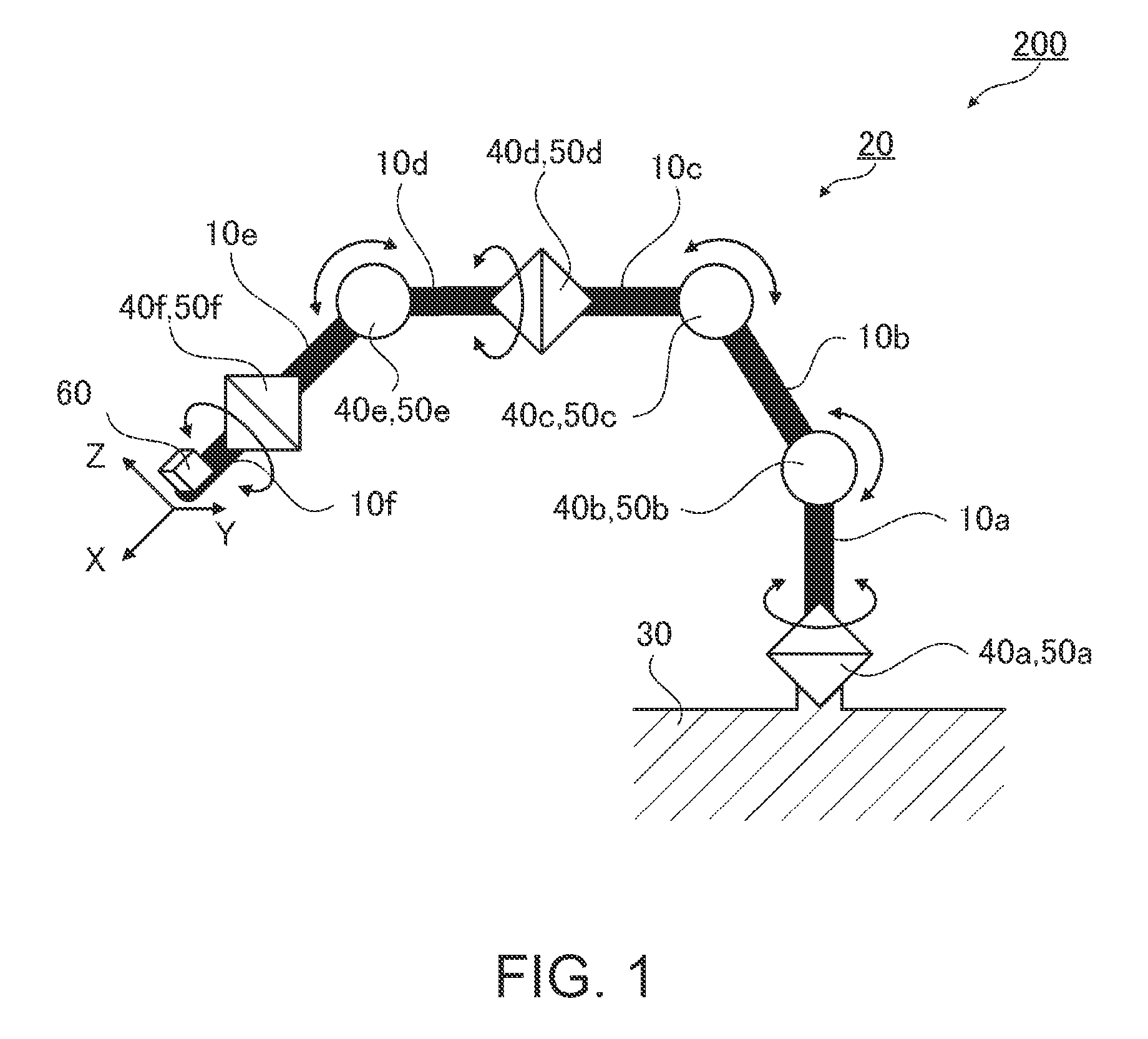
[0040]FIG. 1 is a schematic diagram showing a link model of a robot 200 mounted with the control device for the robot according to the first embodiment. In FIG. 1, the control device for the robot is not shown.

[0041]The robot 200 is a six-axis multi-joint robot. The robot 200 includes an arm 20 including six coupled links 10 (10a to 10f), a robot main body 30 including the arm 20, and six driving units 40 (40a to 40f) configured to respectively drive the links 10.

[0042]In the following explanation, an “arm” includes a “structure in which a plurality of links are coupled”. Coupling sections functioning as joints for coupling the respective links include the driving units having a function of driving the respective links.

[0043]In the arm 20, the six links 10a to 10f are coupled in order via the driving units 40a to 40f. At a distal end portion of the link 10f forming one end of...

second embodiment

[0082]A control device and a control method for a robot according to a second embodiment are explained. In the explanation, components that are the same as the components in the first embodiment are denoted by the same reference numerals and signs and a redundant explanation of the components is omitted.

[0083]FIG. 4 is a schematic diagram showing a link model of a robot 201 mounted with the control device for the robot according to the second embodiment.

[0084]The robot 201 is a six-axis multi-joint robot same as the robot 200 mounted with a damping device 101 (not shown in the figure).

[0085]The damping device 101 is the same as the damping device 100 except that a gyro sensor (hereinafter, inertia sensor 61) that detects angular velocities (Rx′, Ry′, Rz′) of three axes is used as the inertia sensor. In this embodiment, the inertia sensor 61 is attached to the link 10d. That is, whereas the inertia sensor 60 is attached to the link 10f to suppress vibration in the distal end portion ...

third embodiment

[0095]A control device and a control method for a robot according to a third embodiment are explained. In the explanation, components that are the same as the components in the embodiments explained above are denoted by the same reference numerals and signs and a redundant explanation of the components is omitted.

[0096]FIG. 5 is a schematic diagram showing a link model of a robot 202 mounted with the control device of the robot according to the third embodiment.

[0097]The robot 202 is a double-arm multi-joint robot mounted with a damping device 102 (not shown in the figure). The robot 202 includes two arms 21 forming seven-axis double arms, a revolving arm 22, the robot main body 30, and the damping device 102.

[0098]In the arm 21, the seven links 11b to 11h are coupled in order via driving units 41b to 41h. At a distal end portion of the link 11h forming one end of the arm 21, a hand tool, a welding gun, a spray gun, or the like (not shown in the figure) is attached as a hand unit.

[0...


PUM


Abstract

A control method for suppressing vibration of a robot arm including a plurality of coupled links and driving units configured to drive the links includes calculating a first arm speed from at least one of acceleration and an angular velocity detected in a damping position for suppressing vibration, calculating a third arm speed according to the detected first arm speed and a second arm speed in the damping position calculated on the basis of a driving amount of the driving units, and subjecting the driving units to correction control on the basis of the calculated third arm speed.

Description

BACKGROUND[0001]1. Technical Field[0002]The present invention relates to a control device and a control method for a robot and the robot.[0003]2. Related Art[0004]Industrial robots are experiencing heightened demands for increases in speed, functions, accuracy and power savings. In a multi-joint robot manufactured to meet these demands, a reduction in weight for realizing an increase in speed and power savings is generally contrary to an increase in rigidity for realizing an increase in accuracy. As such, both the reduction in weight and the increase in rigidity have been attained through a control technique. For example, JP-A-2011-136395 proposes a method of suppressing the vibration of a robot tip that occurs when the motion of a robot stops. Specifically, JP-A-2011-136395 proposes a method of providing an acceleration sensor at the tip of the robot and adding, on the basis of a detected torsional angular velocity and a detected torsion angle, a compensation amount for eliminating...

Claims


Application Information

Patent Timeline
Patent Type & Authority Patents(United States)
IPC IPC(8): B25J9/16G05B19/404
CPCB25J9/1694B25J9/1641G05B2219/39195G05B2219/40549G05B19/404B25J9/06B25J9/10B25J13/00
Inventor MOTOYOSHI, MASAKI
Owner SEIKO EPSON CORP
Why Eureka
Try Eureka